Assembly aid for printed board connectors

a technology of assembly aid and printed board, which is applied in the direction of gear teeth, coupling device connections, manufacturing tools, etc., can solve the problems of not being able to be removed and structured in a quite complicated fashion

Active Publication Date: 2014-05-27
HARTING ELECTRIC GMBH & CO KG
View PDF24 Cites 4 Cited by
  • Summary
  • Abstract
  • Description
  • Claims
  • Application Information

AI Technical Summary

Benefits of technology

[0007]The invention therefore is based on the objective of realizing an assembly aid for jointly assembling several printed board connectors on a printed board, wherein said assembly aid has a simple design and can be cost-efficiently manufactured.
[0011]In addition, this type of assembly makes it possible to minimize positional tolerances because at least the simultaneously positioned printed board connectors have an exact alignment on the printed board and therefore an equally exact alignment relative to the mating connectors. It simultaneously prevents mechanical stresses between the connectors that could possibly result in shearing loads and cracks at the soldering points that, in turn, could lead to malfunctions of the electronics.
[0013]Printed board connectors with a two-row design have the significant advantage that the soldering points of these contacts on the printed boards can be visually checked to both sides of the connector body while printed board connectors with more than two rows frequently need to be tested with a much more cost-intensive X-ray analysis in order to reliably detect soldering flaws on individual contacts.
[0014]When using two-row printed board connectors, it is necessary to install a larger quantity in order to contact a similar number of contacts on the printed board. The utilization of the inventive assembly aid is very advantageous for simplifying the assembly and for shortening the assembly time.
[0019]Furthermore, the mating side of the printed board connectors can be advantageously protected against dirt accumulation with a protective device in the form of a cover.

Problems solved by technology

Such assembly aids are generally known, but have the disadvantage that they cannot be removed in some cases or are only designed for special arrangements on a printed board and therefore frequently structured in a quite complicated fashion.

Method used


Image

  • Assembly aid for printed board connectors
  • Assembly aid for printed board connectors
  • Assembly aid for printed board connectors

Examples


Embodiment Construction

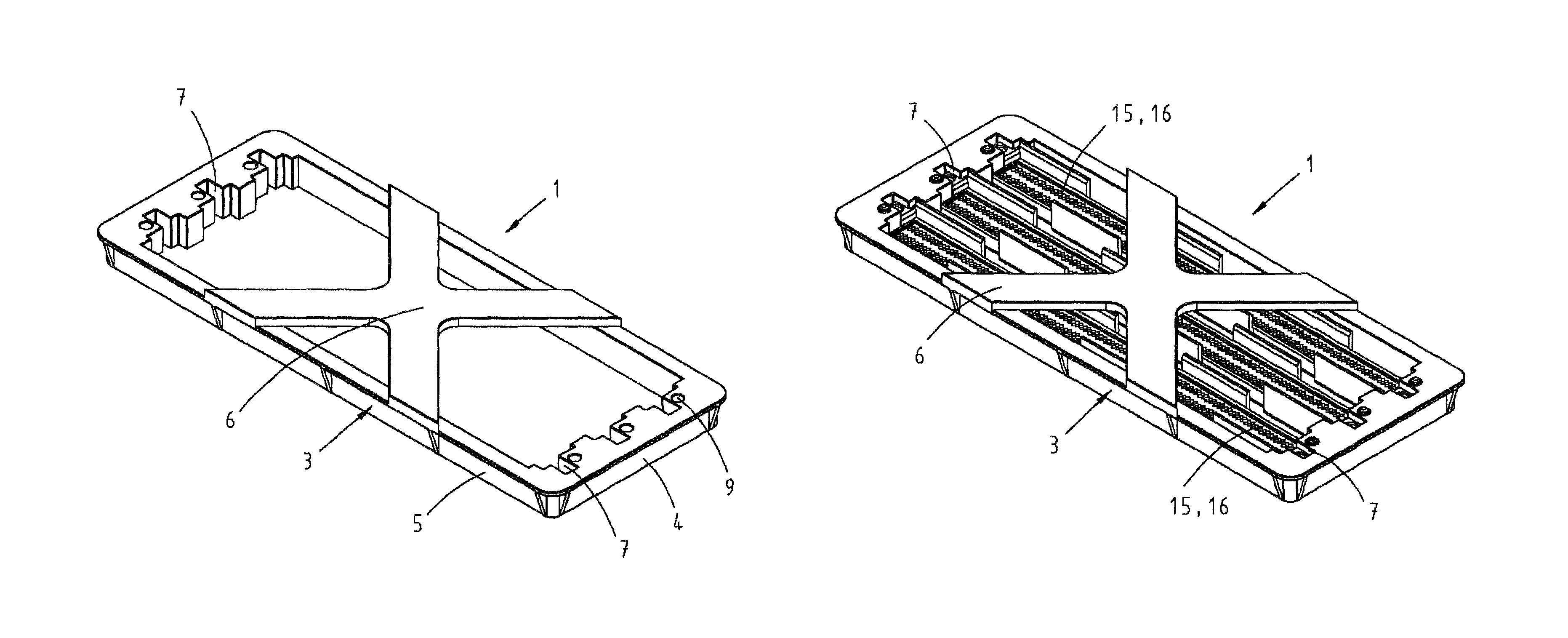
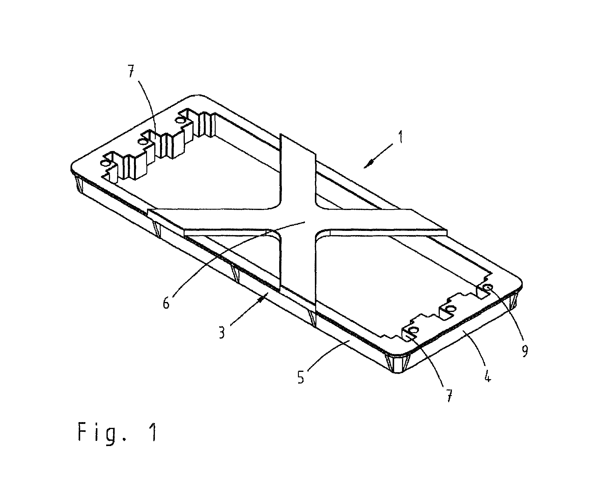
[0028]FIG. 1 shows an assembly aid 1 with an assembly frame 3 for accommodating several printed board connectors.

[0029]The assembly frame 3 is composed of four frame braces, namely two shorter braces 4 and two longer braces 5, wherein intersecting support arms 6 are integrally formed onto two of the oppositely arranged longer braces 5. The shorter braces 4 are provided with opposing recesses 7, into which printed board connectors 15 to be positioned on a printed board are respectively inserted.

[0030]Bores 9 are furthermore arranged in the shorter braces 4, wherein guide pins 8 integrally formed onto the printed board connectors 15 can be inserted into said bores.

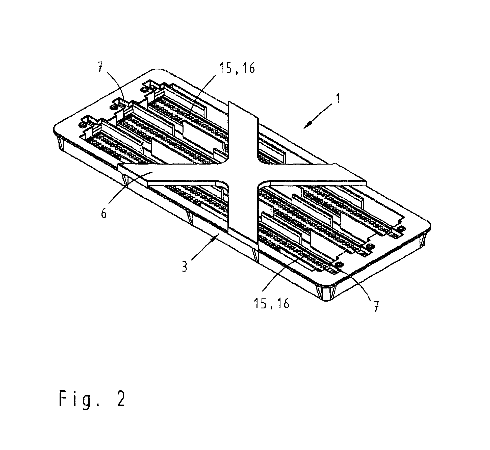
[0031]FIG. 2 shows a correspondingly fitted assembly frame 3 with three printed board connectors 15.

[0032]In this case, the printed board connectors are inserted into the recesses 7 in the assembly frame 3 in such a way that their mating side 16 to be contacted with a corresponding mating connector points in the direction of...


PUM

PropertyMeasurementUnit
dimensionsaaaaaaaaaa
mechanical stressesaaaaaaaaaa
timeaaaaaaaaaa

Abstract

In order to simplify the assembly of printed board connectors, there is provided an assembly aid that features one or more recesses in accordance with the dimensions of the printed board connectors, wherein one or more printed board connectors to be assembled on a printed board can be inserted into said recesses. The contact spacing on the printed board corresponds with the arrangement of the printed board connectors in the assembly aid such that an exact alignment of the printed board connectors is realized. The assembly aid remains on the printed board until the soldering process is completed, wherein this prevents, for example, flotation of SMD components.

Description

BACKGROUND OF THE INVENTION[0001]1. Field of the Invention[0002]The invention pertains to an assembly aid for printed board connectors that serves for accommodating and successively arranging at least one printed board connector to be positioned on a printed board.[0003]An assembly aid of this type is required for jointly positioning several printed board connectors that may also have different dimensions on a printed board, wherein the assembly aid can be removed again after the soldering process.[0004]2. Description of the Related Art[0005]Such assembly aids are generally known, but have the disadvantage that they cannot be removed in some cases or are only designed for special arrangements on a printed board and therefore frequently structured in a quite complicated fashion.[0006]U.S. Pat. No. 5,558,540 discloses a multicontact arrangement, in which two printed board connectors that are spaced apart from one another are arranged in a common frame, wherein a removable holding part...

Claims


Application Information

Patent Timeline
Patent Type & Authority Patents(United States)
IPC IPC(8): B23F19/00
CPCH05K3/00H01R43/205H01R43/28Y10T29/5313Y10T29/53209Y10T29/53174
Inventor SCHUETZ, CHRISTIANPAPE, GUENTER
Owner HARTING ELECTRIC GMBH & CO KG
Why Eureka
Try Eureka