Ball ramp clutch

Active Publication Date: 2014-05-27
HANON SYST EFP CANADA LTD
View PDF16 Cites 8 Cited by
  • Summary
  • Abstract
  • Description
  • Claims
  • Application Information

AI Technical Summary

Benefits of technology

[0037]FIGS. 5-10 depict another electromagnetic clutch identified at reference numeral 220. Clutch 220 is similar to clutch 100 and clutch 200 but includes a number of different features to provide long-term, robust operation.
[0038]Clutch 220 forms part of a pump assembly 221 including a housing 222 rotatably supporting an output shaft 224 w

Problems solved by technology

In particular, to disengage the floating plate from the friction plate, a relativel

Method used


Image

  • Ball ramp clutch
  • Ball ramp clutch
  • Ball ramp clutch

Examples


Embodiment Construction

[0025]Example embodiments will now be described more fully with reference to the accompanying drawings.

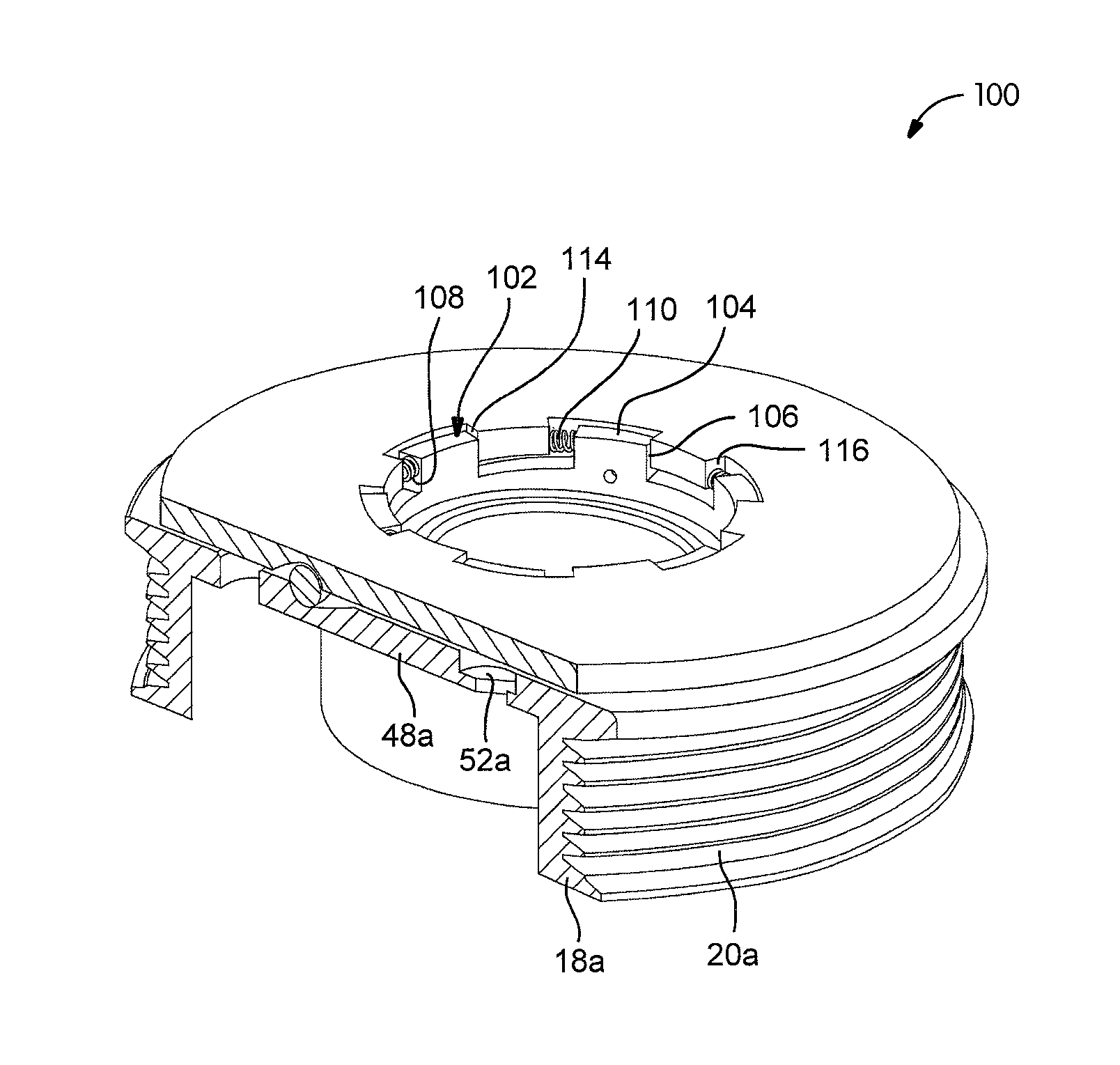
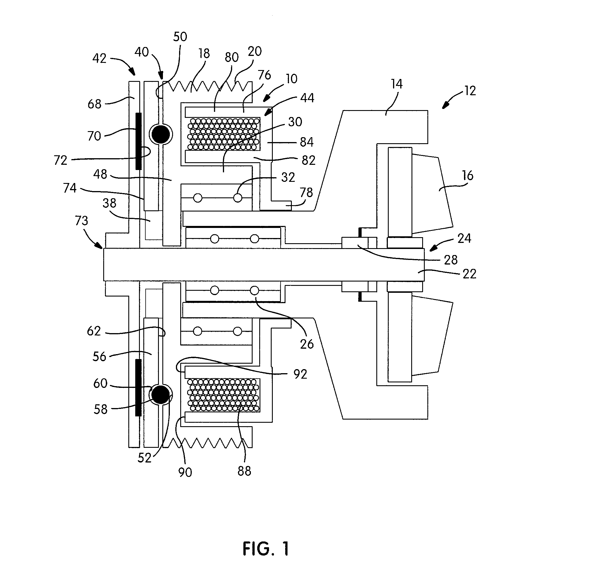
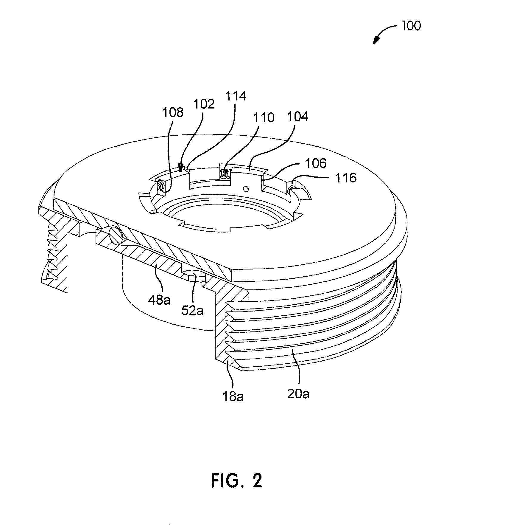
[0026]FIG. 1 provides a cross-sectional view of an electromagnetic clutch 10 associated with an exemplary water pump 12. Water pump 12 includes a housing 14 and a rotatable impeller 16. It should be appreciated that water pump 12 is merely an exemplary driven load and any number of other automobile accessories or subsystems may be in receipt of power transferred through clutch 10. A rotatable input shaft 18 provides torque input to clutch 10 and includes a driven pulley 20 in the example depicted in FIG. 1. Input power may be transferred to clutch 10 via any number of other mechanical elements including sprockets, gears, chains, belts or the like. Pulley 20 is configured to be driven by a flexible belt coupled to an output shaft of an internal combustion engine (not shown). A rotatable output shaft 22 includes an end 24 fixed for rotation with impeller 16. Output shaft 22 is suppor...


PUM


Abstract

An electromagnetic clutch includes a rotatable input member and a rotatable output member. A clutch plate is fixed for rotation with one of the input member and the output member. An armature plate is axially moveable relative to the other of the input member and the output member. A self-energizing actuator converts rotary motion of the input member to linear movement of the armature plate. The actuator includes a biasing member urging relative rotation between the one of the input member and the output member and the armature plate to initially engage the armature plate and the clutch plate. The self-energizing actuator provides an additional clutch engagement force once the input member is driven and also includes an electromagnet to axially translate the armature plate and disengage the armature plate and the clutch plate.

Description

CROSS-REFERENCE TO RELATED APPLICATIONS[0001]This application claims the benefit of U.S. Provisional Application No. 61 / 219,472, filed on Jun. 23, 2009. The entire disclosure of the above application is incorporated herein by reference.FIELD[0002]The present disclosure relates to a clutch and a clutch actuator. More particularly, a clutch actuator includes a dual input force mechanism including a biasing member and an incline plane such that torque transferred by the clutch provides a majority of the clutch actuation input force. The clutch is deactuated by an electro-magnet.BACKGROUND[0003]Electromagnetic clutches have been utilized commercially in a variety of applications, including automobiles. Typically, an electromagnetic clutch includes a rotor having an inner annular bearing portion, a clutch portion extending generally radially outwardly from one end of the inner portion and an outer annular portion extending from the clutch portion in a generally overlying spaced relation ...

Claims


Application Information

Patent Timeline
IPC IPC(8): F16D13/42F16D13/04
CPCF16D27/004F04D13/027F16D2023/123F04D13/02F02B67/04F16D27/112
Inventor GREENE, DARRELL, F.
Owner HANON SYST EFP CANADA LTD
Why Eureka
Try Eureka