Method and apparatus for communicating between a security module and a host device

a security module and host device technology, applied in the field of methods and apparatus for communicating between a security module and a host device, can solve the problems of unscrupulous third parties attempting to compromise the security of the system, and unscrupulous third parties may attempt to secure features such as encryption keys, so as to reduce the amount of electromagnetic interference, and reduce the effect of electromagnetic interferen

Active Publication Date: 2014-05-27
NAGRAVISION SA
View PDF7 Cites 0 Cited by
  • Summary
  • Abstract
  • Description
  • Claims
  • Application Information

AI Technical Summary

Benefits of technology

[0014]The amount of EMI coming from a system depends partly on the frequency at which the system operates (the higher the frequency, the higher the level of EMI), the number of nodes within the system which operate at that frequency (each of such nodes adding a component to the total EMI) and the length of wire that such a node represents (the longer the wire, the more EMI it will radiate). On the other hand, in order for the security module to be able to operate such that optimum system performance is achieved, it must be able to operate at sufficiently high frequencies, such sufficiently high frequencies often being those which are susceptible to generating adverse amounts of EMI with respect to the ability of the eavesdropping third party to reconstruct a communication. It is therefore important that at least the security module operate at an optimum frequency, the optimum frequency being that which is sufficiently high to achieve a predetermined optimum system performance. For a system comprising a security module configured to operate at a predetermined optimum frequency, a goal of the present invention is therefore to reduce the number of wires in the system which operates at the optimum frequency. Another goal is to minimize the lengths of wires which operate at the optimum frequency. According to an embodiment of the present invention, only the clock pin and the data pin of the security module operate at the optimum frequency. Known measures can then be taken to minimize the remaining EMI coming from the clock pin and the data pin.
[0016]In view of the prior art, it is an aim of the present invention to provide a means for reducing the amount of electromagnetic interference detectable from the outside of a host device while the host device is communicating with a security module, especially when the host device comprises a slot or port through which the security module is inserted. Implementation of embodiments of the present invention allow for reduction of EMI generated by a security module performing operations while in the host device to a level which precludes a third party from being able to reconstruct said operations based on detection of the EMI.
[0017]It is a further aim of the present invention to provide a means for reducing the amount of electromagnetic interference escaping from a security module towards electronic components comprised within a host device while the security module is communicating with the host device.
[0018]It is a further aim of the present invention to provide for such reduction in electromagnetic interference while retaining ease of physical access to the host device by the security module, thereby allowing ease of exchanging one security module for another. This requirement therefore precludes the possibility of using a port cover or a flexible envelope as described in the prior art as well as the use of screening layers around the security module. Additionally, an aim of the present invention is to reduce the manufacturing costs associated with the production of host devices intended to receive security modules which function at operating frequencies high enough to generate the undesired EMI and therefore the use of expensive screening layers such as those described in the prior art is not a desired option.

Problems solved by technology

Secure processes include the storage and the use of encryption keys, the disclosure of which would break the security of the system.
In seeking to break the security of the system, unscrupulous third parties may attempt to security features such as encryption keys.

Method used


Image

  • Method and apparatus for communicating between a security module and a host device
  • Method and apparatus for communicating between a security module and a host device
  • Method and apparatus for communicating between a security module and a host device

Examples


Embodiment Construction

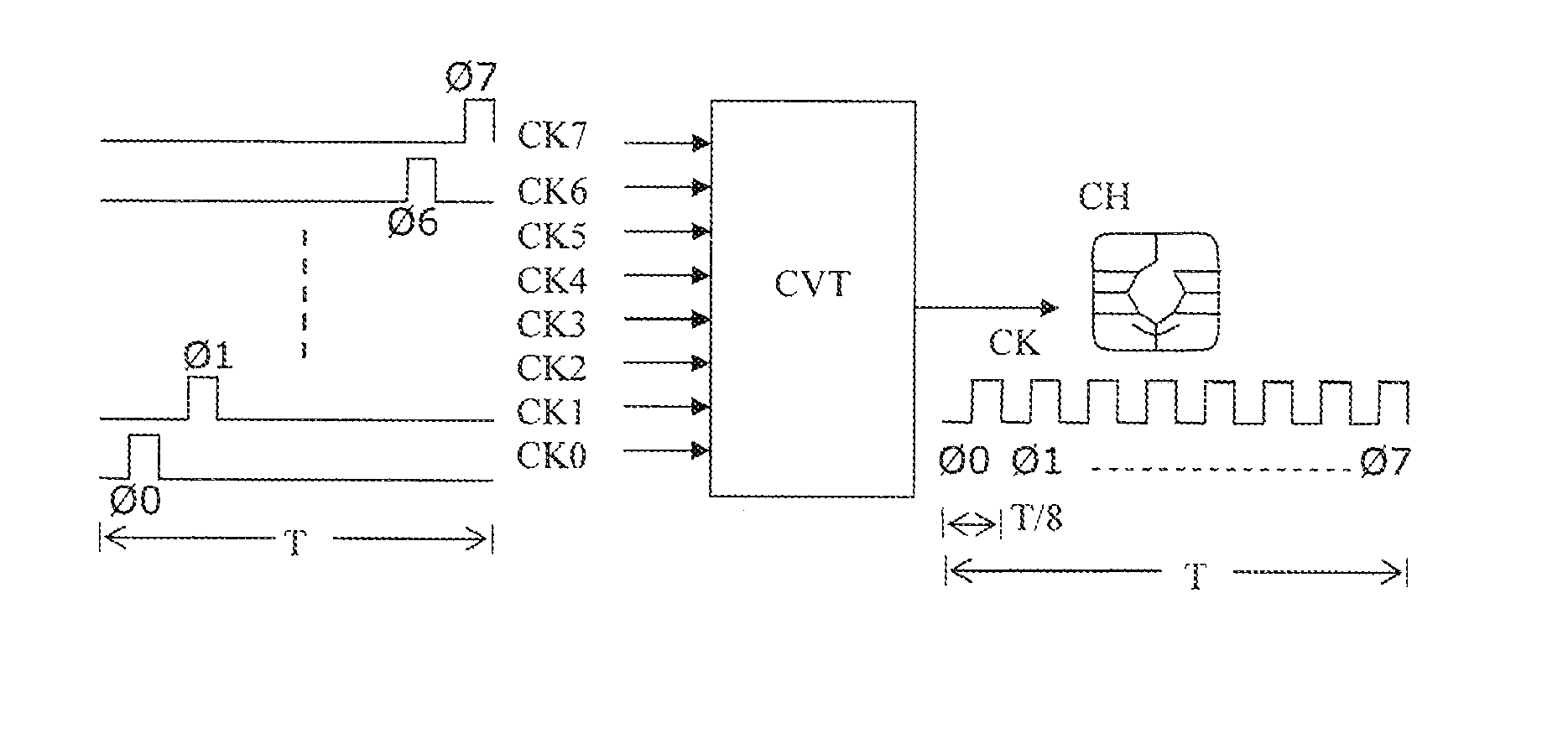
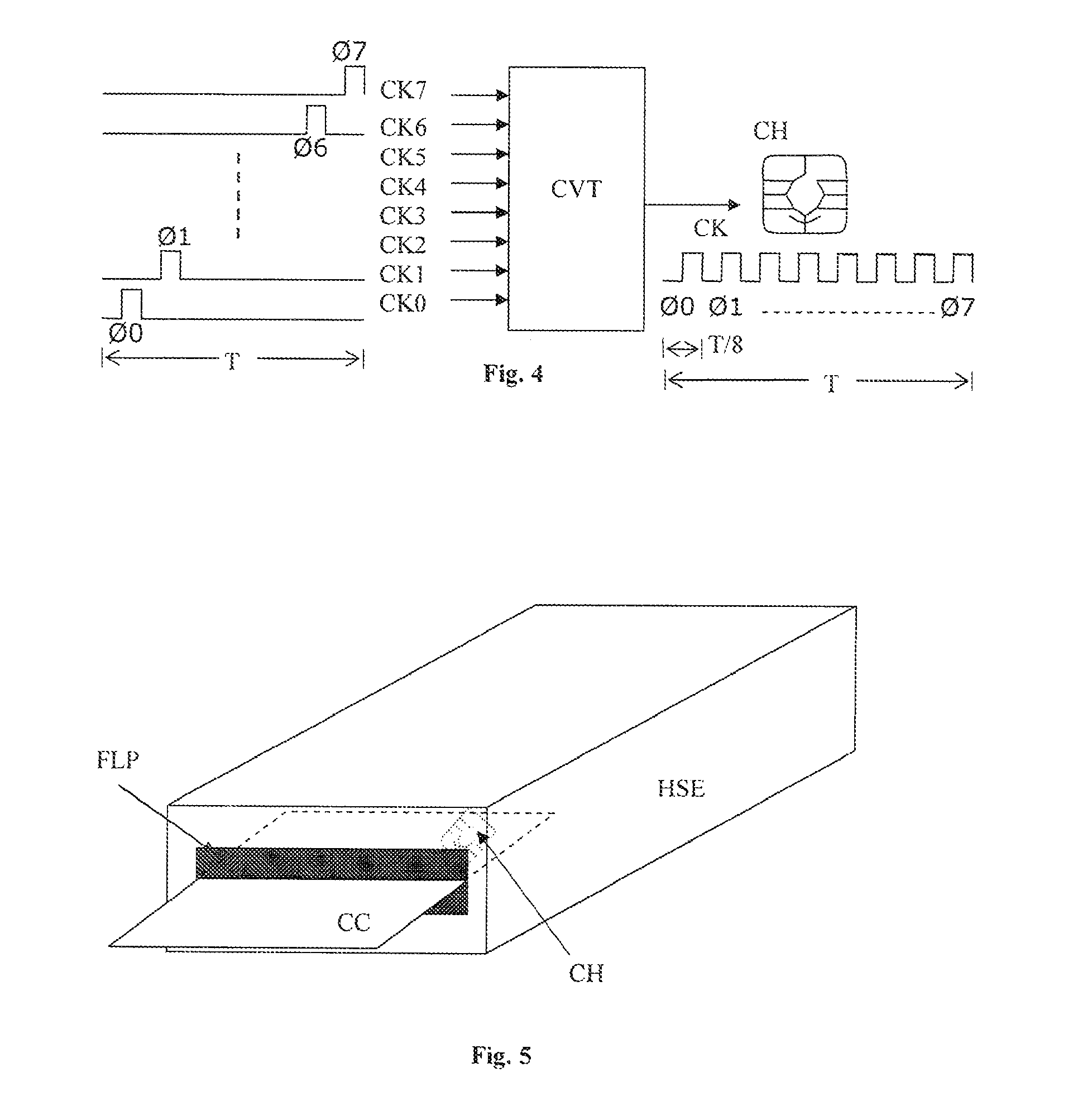
[0032]It is well known to those who are familiar with the domain of radio frequency (RF) electromagnetic interference (EMI) that a contributory variable in determining the amount of EMI that will be emitted from a wire is proportional to the length of that wire and that another contributory variable is the frequency content of a signal transported by the wire. In a preferred embodiment of the present invention it is therefore sought to minimise the length of any wires which carry such signals with high frequency content in the host device / security module ensemble and to minimise the number of such wires.

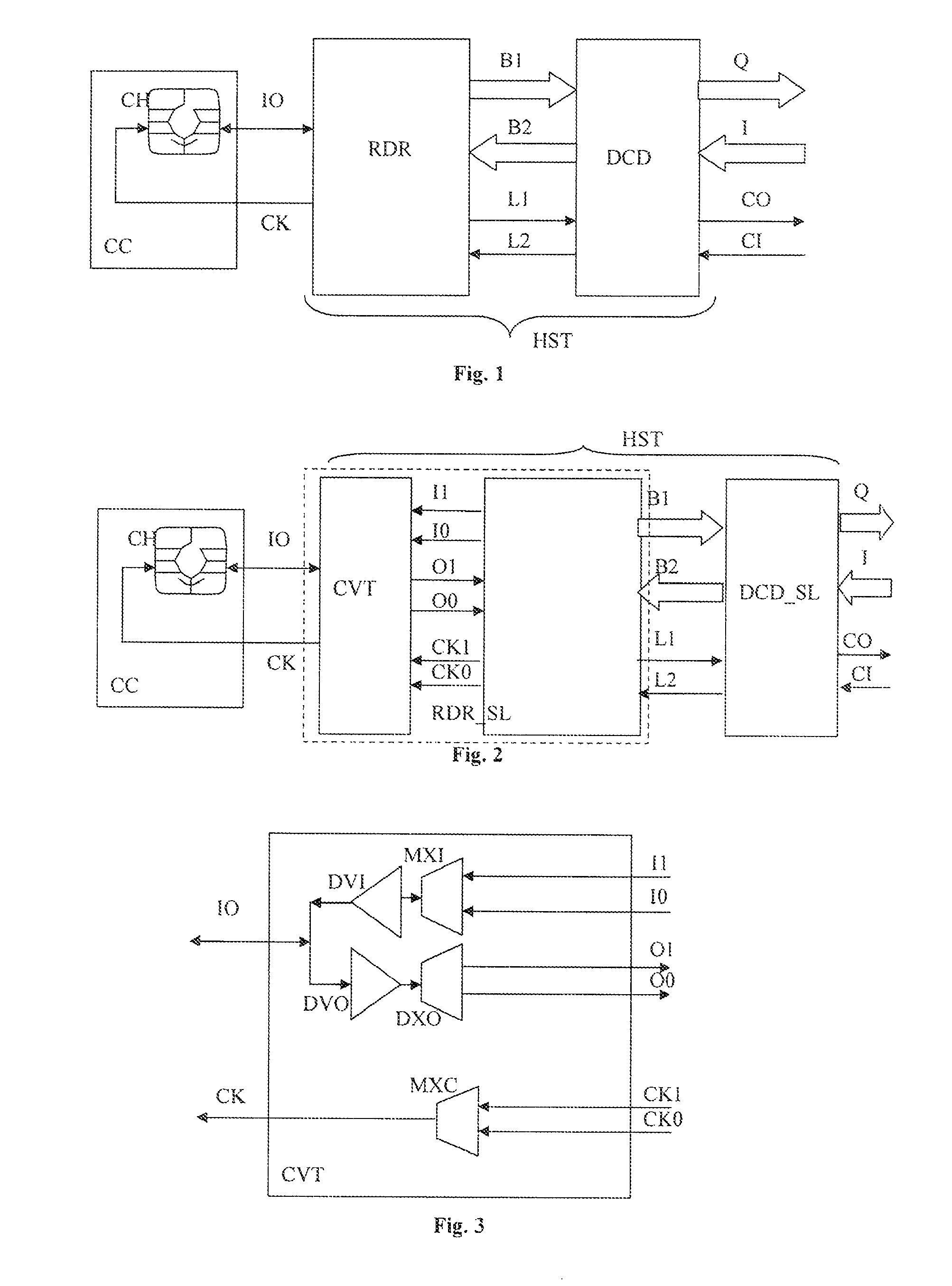
[0033]FIG. 1 shows a security module connected to a host device. The security module is in the form of an electronic chip (CH) housed on a chip card (CC). This configuration is generally known in the state of the art. The security module or chip (CH) on its chip card (CC) is inserted into a slot in the host device (HST) and the chip's contact pads enter into contact with a set of con...


PUM


Abstract

The present invention may be deployed in an interface between a security module (CH) housed on a chip card (CC) and a host device (HST) comprising a chip card reader (RDR). In the case where the security module (CH) operates at frequencies which are high enough to generate unwanted electromagnetic interference, the invention allows for a substantial reduction in such interference by providing a converter module (CVT) which allows the host device to operate at lower frequencies while a limited number of short, shielded connections are used to interface with the security module (CH).

Description

CROSS REFERENCE TO RELATED APPLICATIONS[0001]This application claims priority under 35 U.S.C. Section 119 to U.S. Provisional Application No. 61 / 414,909, filed Nov. 18, 2010, the entire contents of which are hereby incorporated by reference herein.INTRODUCTION[0002]The present invention relates to the domain of radio frequency electromagnetic interference and more specifically to methods and devices for the reduction of such interference in electronic circuits.STATE OF THE ART[0003]With the increasing use of higher and higher signal frequencies in the operation of electronic circuits, the problems related to electromagnetic interference or EMI are becoming more acute. In the domain of conditional access, the use of a security module is commonplace. A security module is usually used in cooperation with a host device which comprises at least a card reader to interface with the security module. The host device may further comprise a cryptographic module and other related conditional ac...

Claims


Application Information

Patent Timeline
Patent Type & Authority Patents(United States)
IPC IPC(8): G06K7/06
CPCG06K7/10257G06K19/07336
Inventor OSEN, KARLODOOM, ERNEST
Owner NAGRAVISION SA
Why Eureka
Try Eureka