Transformable and reconfigurable entry, descent and landing systems and methods

a technology of aerodynamic decelerator and transformable configuration, applied in the field of transformable and reconfigurable aerodynamic decelerator system, can solve the problems of severe entry condition, insufficient density of atmosphere, and limited mass of payload for which rigid aeroshell structure is designed

Active Publication Date: 2014-05-27
NASA
View PDF6 Cites 22 Cited by
  • Summary
  • Abstract
  • Description
  • Claims
  • Application Information

AI Technical Summary

Benefits of technology

[0006]Further, typical EDL technologies utilize a reaction control system (RCS) using propulsive thrust for directional control of the payload during descent. However, conventional propulsive thrust technologies may be inefficient and inadequate for large payloads.

Problems solved by technology

Due to such size limitations of the rigid aeroshell structure, the mass of the payload for which the rigid aeroshell structure is designed is also limited.
The limitations of size and the resulting mass that can be packaged within the rigid aeroshell structure often results in a severe entry condition.
For a planet such as Mars, the atmosphere is not dense enough to allow typical rigid aeroshell structures to be effective for payloads over approximately two metric tons (mT).
However, the Martian atmosphere is dense enough to cause significant heating from aerodynamic friction during descent.
However, conventional propulsive thrust technologies may be inefficient and inadequate for large payloads.

Method used


Image

  • Transformable and reconfigurable entry, descent and landing systems and methods
  • Transformable and reconfigurable entry, descent and landing systems and methods
  • Transformable and reconfigurable entry, descent and landing systems and methods

Examples


Embodiment Construction

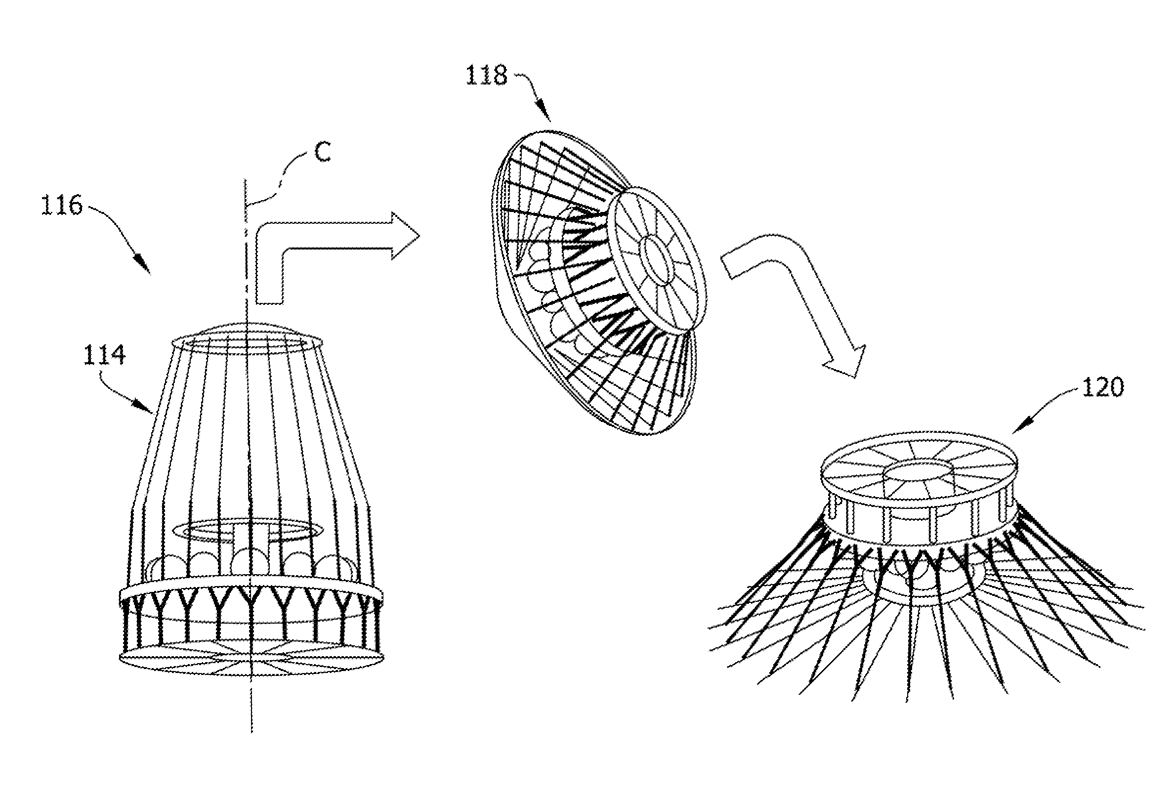
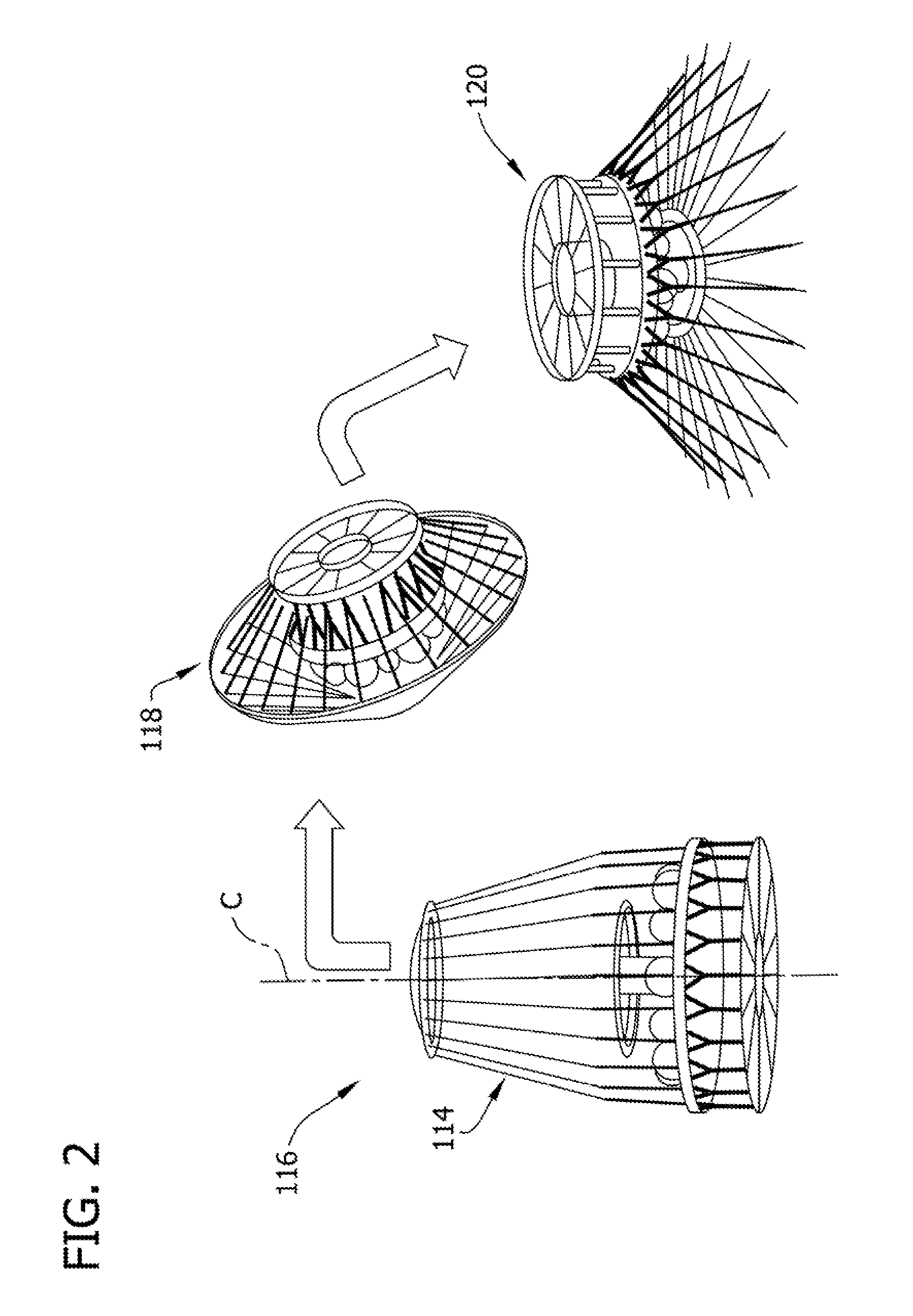
[0021]The transformable and reconfigurable aerodynamic decelerator systems of the present disclosure are stowable within an air vehicle or launch vehicle. For example, the aerodynamic decelerators are deployable into a large aerosurface for aerocapture and atmospheric entry and descent. The aerodynamic decelerator systems are, in one embodiment, reconfigurable for efficient control during flight and include thermal protection materials. The aerodynamic decelerator systems, in another embodiment, are transformable into a final landing configuration. The aerodynamic decelerator systems described herein may also be referred to as Adaptive DEployable Placement Technology (ADEPT).

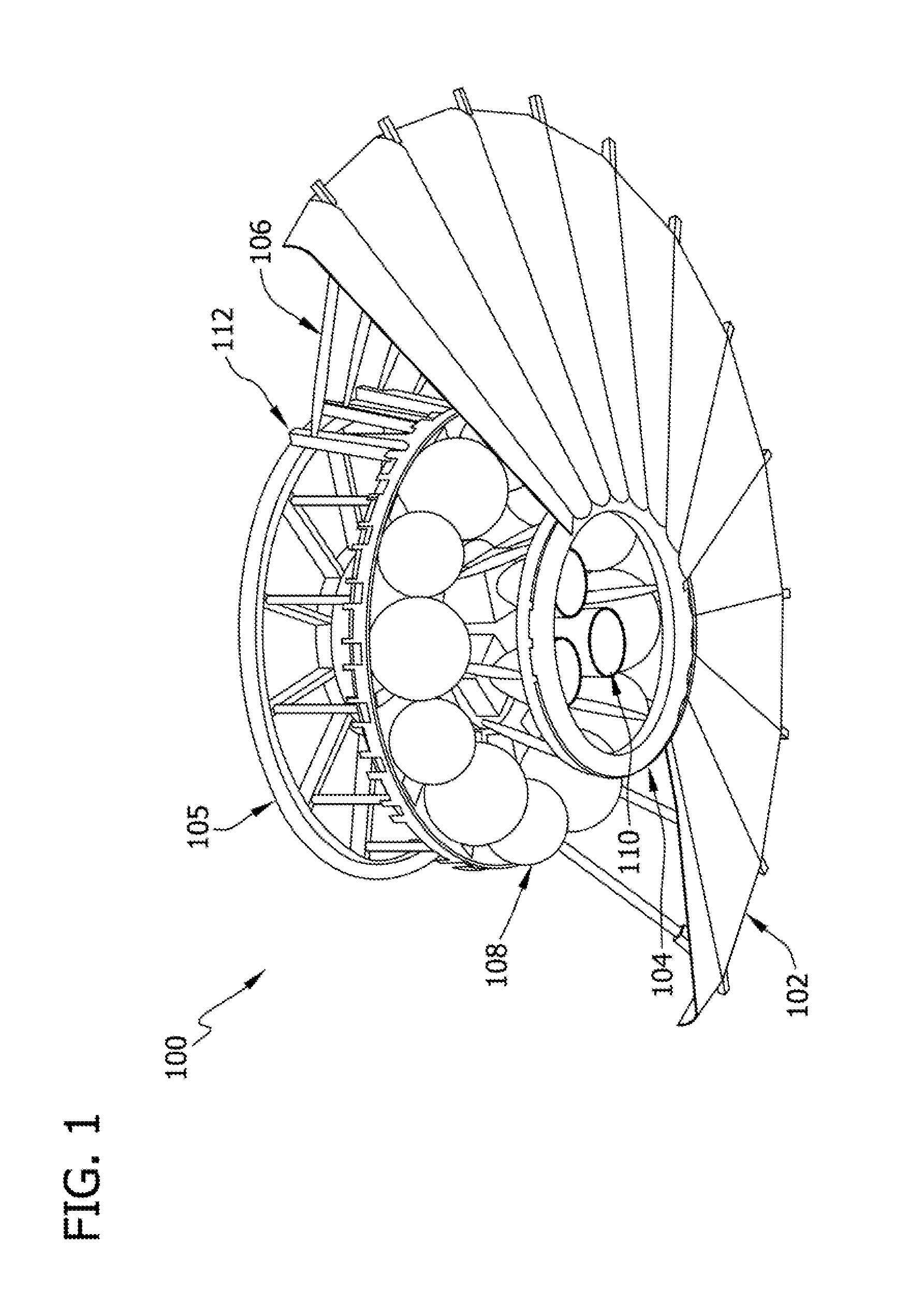
[0022]Shown generally in FIG. 1 is an exemplary embodiment of an aerodynamic decelerator 100 according to the present disclosure. The aerodynamic decelerator includes a flexible layer 102, ring member 104, payload adaptor member 105, a plurality of links 106, a plurality of fuel storage containers 108, a retro p...


PUM


Abstract

A deployable aerodynamic decelerator structure includes a ring member disposed along a central axis of the aerodynamic decelerator, a plurality of jointed rib members extending radially from the ring member and a flexible layer attached to the plurality of rib members. A deployment device is operable to reconfigure the flexible layer from a stowed configuration to a deployed configuration by movement of the rib members and a control device is operable to redirect a lift vector of the decelerator structure by changing an orientation of the flexible layer.

Description

ORIGIN OF INVENTION[0001]The invention described herein was made by employees of the United States Government and may be manufactured and used by or for the Government of the United States of America for governmental purposes without the payment of any royalties thereon or therefor.TECHNICAL FIELD OF THE INVENTION[0002]The present disclosure relates generally to aerodynamic decelerators. More particularly, the present disclosure relates to transformable and reconfigurable, aerodynamic decelerator systems.BACKGROUND OF THE INVENTION[0003]Conventionally, entry, descent and landing (EDL) technology utilizes a rigid aeroshell structure for both aerodynamic braking and thermal protection of a payload. Typically, the rigid aeroshell structure has a size that is constrained by the launch vehicle carrying the rigid aeroshell structure (i.e., the size is constrained to a size that fits within the launch vehicle). Due to such size limitations of the rigid aeroshell structure, the mass of the ...

Claims


Application Information

Patent Timeline
Patent Type & Authority Patents(United States)
IPC IPC(8): B64C1/10
CPCB64C1/10B64G1/58B64G1/222B64G1/62
Inventor FERNANDEZ, IAN M.VENKATAPATHY, ETHIRAJHAMM, KENNETH R.
Owner NASA
Why Eureka
Try Eureka