Optical scanning apparatus and color image forming apparatus therewith

a scanning apparatus and color image technology, applied in the field of optical scanning apparatus, can solve the problems of insufficient application to an anamorphic, inability to detect the laser amount of each laser beam correctly, and the inability of af sensor to be used as both suitable for detecting the light amount and the light receiving timing, so as to increase the use life of a semiconductor laser and reduce the emission time

Inactive Publication Date: 2014-05-27
CANON KK
View PDF16 Cites 2 Cited by
  • Summary
  • Abstract
  • Description
  • Claims
  • Application Information

AI Technical Summary

Benefits of technology

[0014]The present invention provides an optical scanning apparatus and a color image forming apparatus therewith, which are capable of increasing use life of a semiconductor laser by decreasing the emission time for sensors that are independently provided for the synchronous control, the light control, and the focus control.
[0018]According to the present invention, the use life of the semiconductor laser is increased by decreasing the emission time for sensors that are independently provided for the synchronous control, the light control, and the focus control.

Problems solved by technology

However, the configuration disclosed in this publication cannot detect the laser amount of each laser beam correctly, particularly when a plurality of laser beams are used, because the scanning speed of the laser beam that runs across the sensor is too high.
However, since the technique of JP 2008-122613A only detects the defocus amount in the principal scanning direction, it is insufficient for applying to an anamorphic optical system in which powers are different in a principal scanning direction and an auxiliary scanning direction.
However, since the AF sensor is not suitable for detecting the light amount of the laser beam and the light receiving timing in the configuration that detects the defocus amount by dividing the laser beam as disclosed in JP 2010-096898A, the AF sensor cannot be used as both suitable for detecting the light amount and the light receiving timing of a laser beam, and the AF sensor cannot be used as a BD sensor or an APC sensor.
Accordingly, the emission time of the light emission unit with a semiconductor laser increases, which causes a problem of shortening the use life of the semiconductor laser.

Method used


Image

  • Optical scanning apparatus and color image forming apparatus therewith
  • Optical scanning apparatus and color image forming apparatus therewith
  • Optical scanning apparatus and color image forming apparatus therewith

Examples


Embodiment Construction

[0033]Hereafter, embodiments according to the present invention will be described in detail with reference to the drawings.

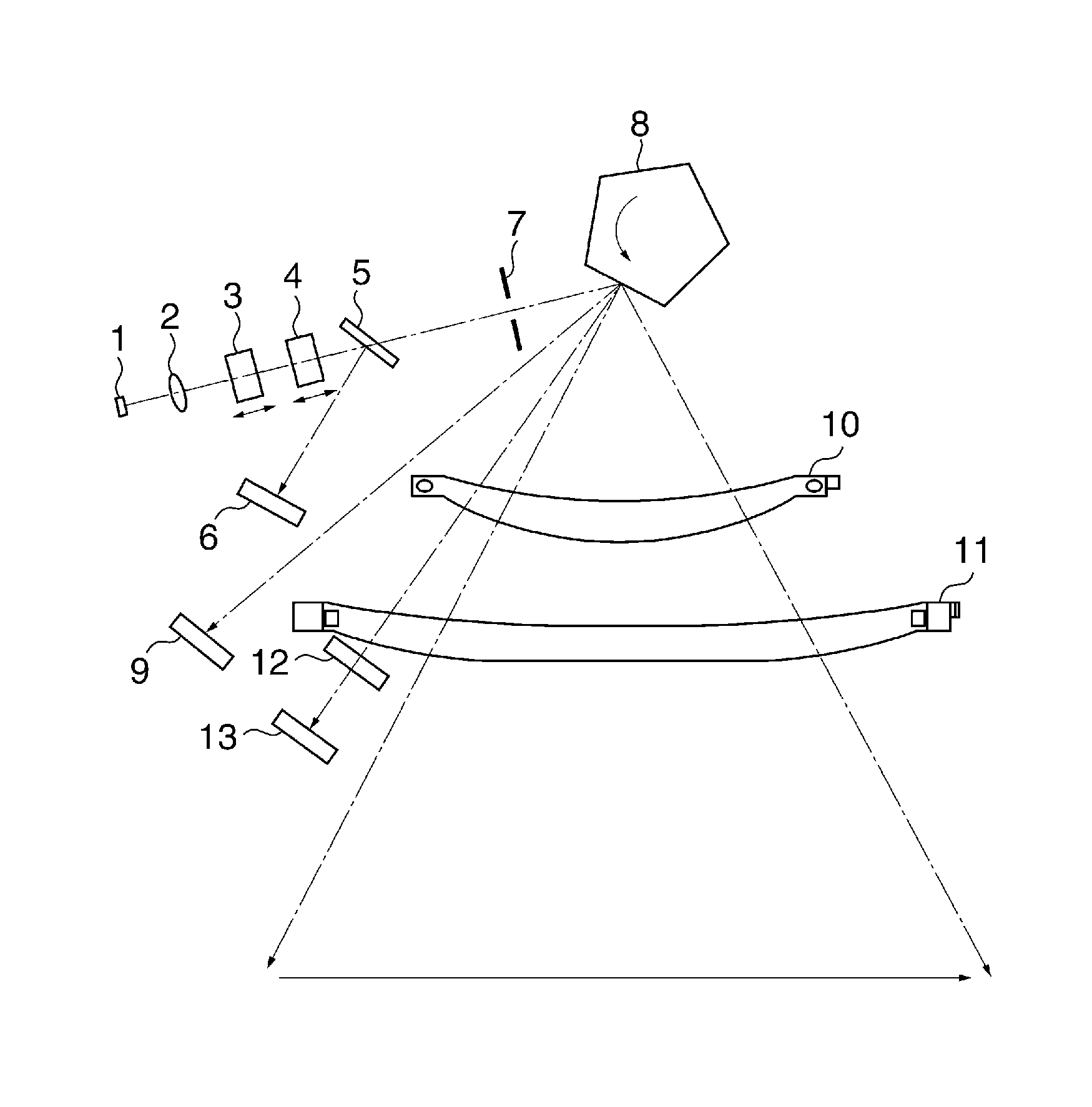
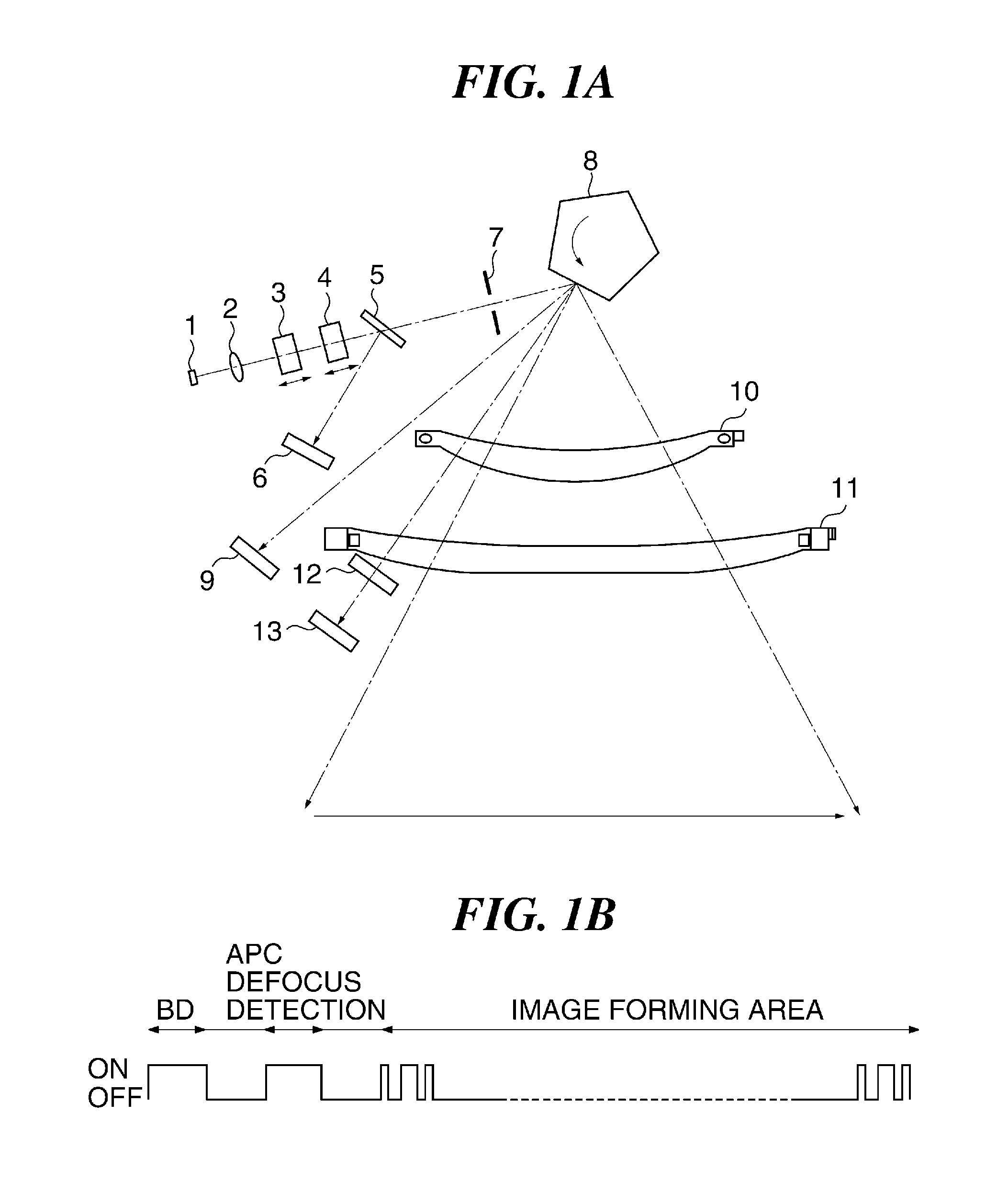
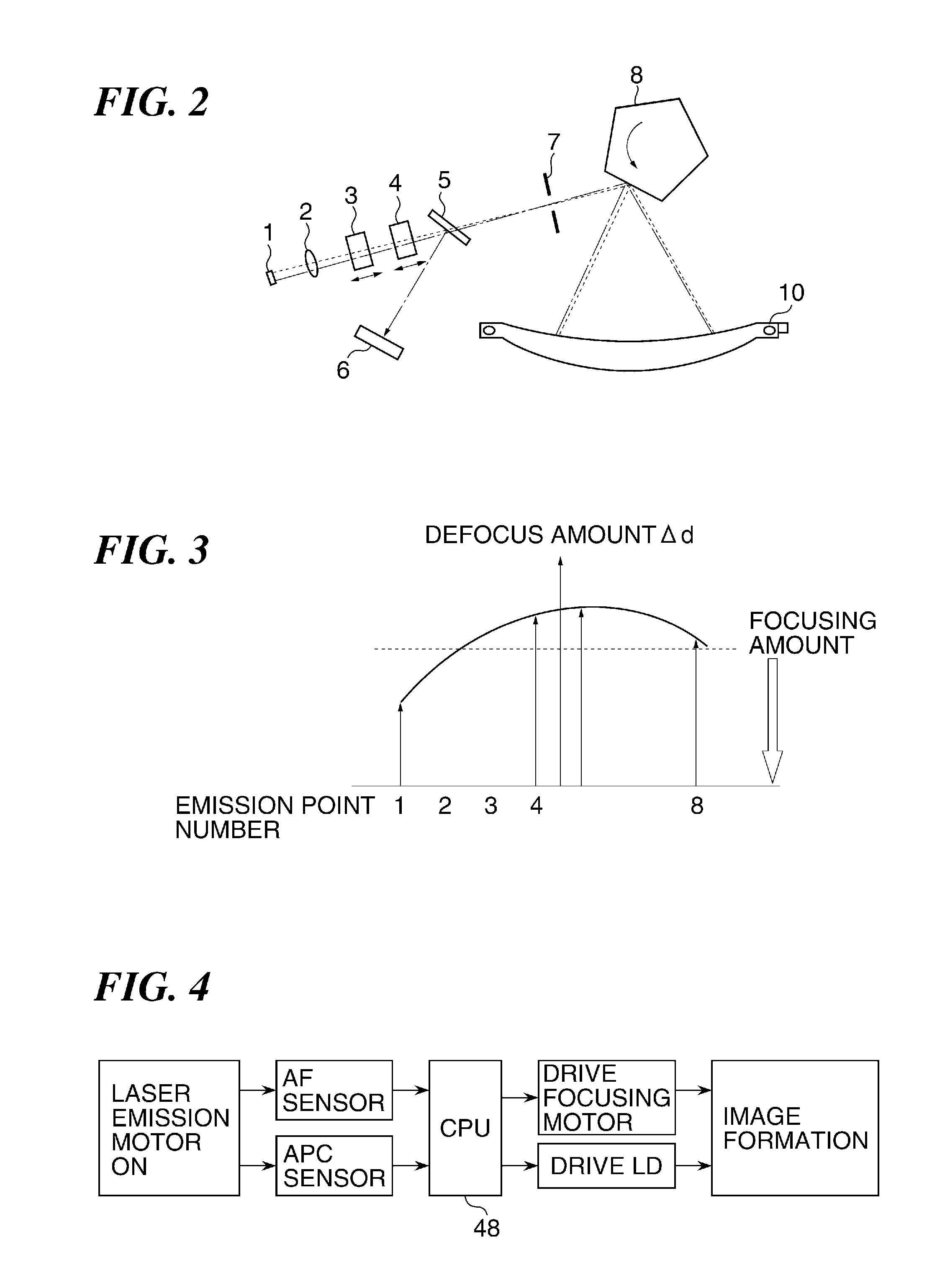
[0034]An optical system of an optical scanning apparatus according to the embodiment is provided with a laser light source 1 including a semiconductor laser that emits a laser beam based on image information, a collimator lens 2 that converts the laser beam emitted from the light emitting unit 1 into a parallel beam, a first cylindrical lens 3 that is supported so as to be movable in an optical axis direction and has refractive power in a principal scanning direction, a second cylindrical lens 4 that is supported so as to be movable in the optical axis direction and has refractive power in an auxiliary scanning direction, and a beam splitter that partially reflect the laser beam as shown in FIG. 1. This optical system is further provided with a light amount detection sensor (an APC sensor, a first detection unit) 6 that detects the light amount of the laser beam...


PUM


Abstract

An optical scanning apparatus that is capable of increasing use life of a semiconductor laser by decreasing the emission time for sensors that are independently provided for synchronous control, light control, and focus control. A laser beam emitted from a light source is deflected by a deflector, and scans a photoconductor. A beam splitter arranged between the light source and the deflector separates the laser beam, which is detected by a first detection unit. A second detection unit arranged in a non-image forming area detects the deflected laser beam to detect defocus amount. A focusing unit focuses the scanning laser beam based on a detection result of the second detection unit. A control unit controls the light amount of the laser beam applied to an image forming area based on a detection result of the first detection unit at the timing when the second detection unit detects the laser beam.

Description

BACKGROUND OF THE INVENTION[0001]1. Field of the Invention[0002]The present invention relates to an optical scanning apparatus with a semiconductor laser, and a color image forming apparatus that is provided with this optical scanning apparatus like a copying machine or a printer with an electrophotography system.[0003]2. Description of the Related Art[0004]An optical scanning apparatus that is mounted in an image forming apparatus for printing an image using an electrophotography process is generally configured to reflect a laser beam emitted from a light emission unit by a rotating polygon mirror, and to form a linear electrostatic latent image by scanning a photoconductive drum with a spot formed on the photoconductive drum through an fθ lens.[0005]Such an optical scanning apparatus is provided with a BD sensor that detects light receiving timing of the laser beam at a position outside a image forming area in order to acquire a synchronized signal for determining a rendering star...

Claims


Application Information

Patent Timeline
Patent Type & Authority Patents(United States)
IPC IPC(8): B41J2/435
CPCG03G15/04072G03G15/0435
Inventor NAKAHATA, HIROSHI
Owner CANON KK
Why Eureka
Try Eureka