Vapor condenser with three-dimensional folded structure

a vapor condenser and three-dimensional technology, applied in the direction of indirect heat exchangers, laminated elements, lighting and heating apparatuses, etc., can solve the problems of increasing component temperature, thermal runaway conditions, increasing power dissipation, and therefore heat production

Active Publication Date: 2014-06-03
IBM CORP
View PDF53 Cites 31 Cited by
  • Summary
  • Abstract
  • Description
  • Claims
  • Application Information

AI Technical Summary

Benefits of technology

[0005]Additional features and advantages are realized through the techniques of the present invention. Other embodiments and aspects of the invention are described in detail herein and are considered a part of the claimed invention.

Problems solved by technology

This heat should be removed in order to maintain device junction temperatures within desirable limits, with failure to remove heat effectively resulting in increased component temperatures, potentially leading to thermal runaway conditions.
First, power dissipation, and therefore heat production, increases as device operating frequencies increase.
Further, as more and more devices or components are packed onto a single chip, heat flux (Watts / cm2) increases, resulting in the need to remove more power from a given size chip or module.
These trends have combined to create applications where it is no longer desirable to remove heat from modern devices solely by traditional air cooling methods, such as by using air cooled heat sinks with heat pipes or vapor chambers.
Such air cooling techniques are inherently limited in their ability to extract heat from an electronic component with high power density.
Water-based coolants, however, must be kept from physical contact with electronic devices and interconnects, since corrosion and electrical short circuit problems are otherwise likely to result.

Method used


Image

  • Vapor condenser with three-dimensional folded structure
  • Vapor condenser with three-dimensional folded structure
  • Vapor condenser with three-dimensional folded structure

Examples


Embodiment Construction

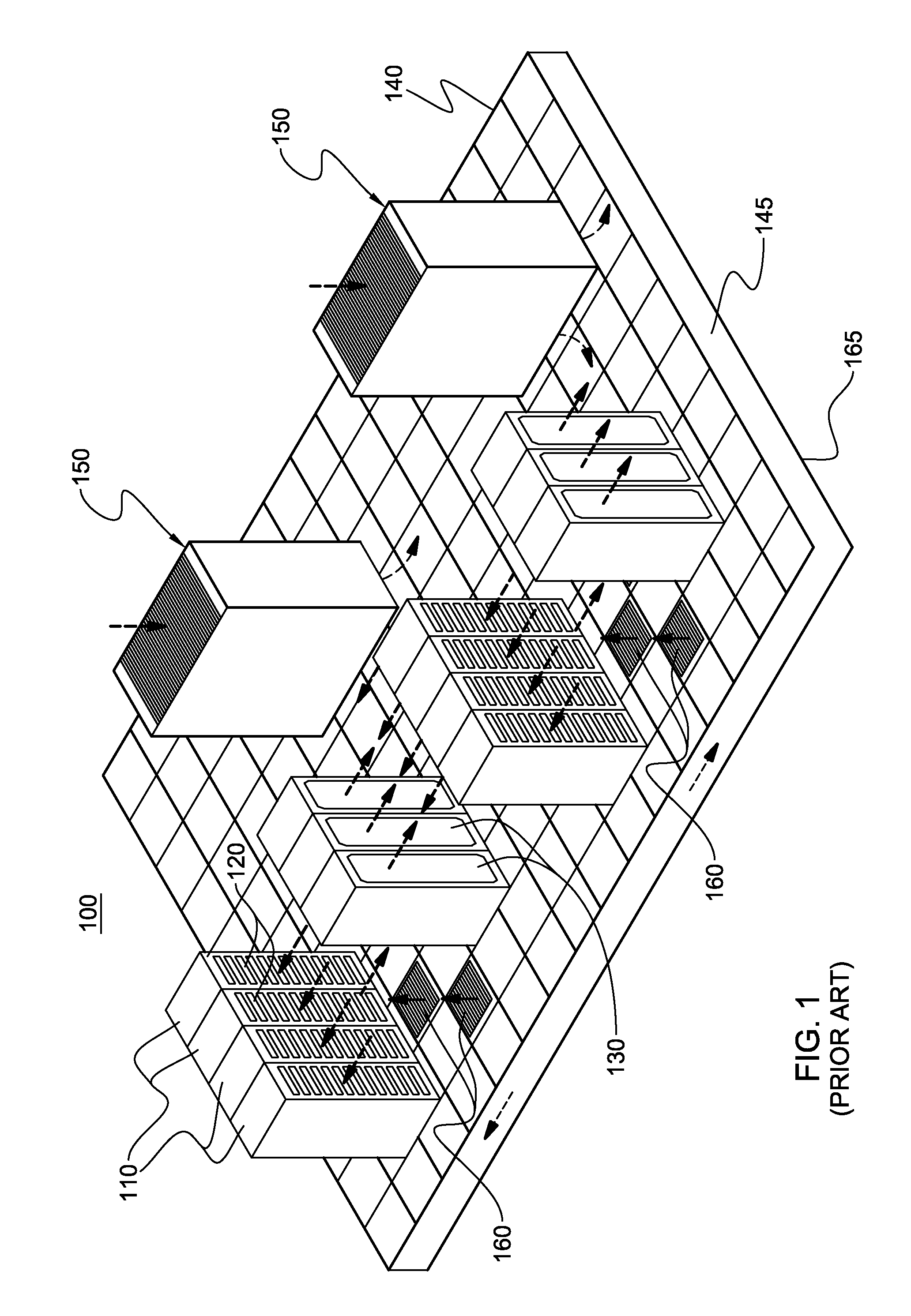
[0020]As used herein, the terms “electronics rack”, “rack-mounted electronic equipment”, and “rack unit” are used interchangeably, and unless otherwise specified include any housing, frame, rack, compartment, blade server system, etc., having one or more heat-generating components of a computer system, electronic system, or information technology equipment, and may be, for example, a stand-alone computer processor having high-, mid- or low-end processing capability. In one embodiment, an electronics rack may comprise one or more electronic subsystems. “Electronic subsystem” refers to any sub-housing, blade, book, drawer, node, compartment, board, etc., having one or more heat-generating electronic components disposed therein or thereon. An electronic subsystem of an electronics rack may be movable or fixed relative to the electronics rack, with the rack-mounted electronic drawers of a rack unit and blades of a blade center system being two examples of subsystems of an electronics ra...


PUM

PropertyMeasurementUnit
temperatureaaaaaaaaaa
thermally conductiveaaaaaaaaaa
condensation surface areaaaaaaaaaaa

Abstract

A method of fabricating a vapor condenser is provided which includes a three-dimensional folded structure which defines, at least in part, a set of coolant-carrying channels and a set of vapor condensing channels, with the coolant-carrying channels being interleaved with and extending parallel to the vapor condensing channels. The folded structure includes a thermally conductive sheet with multiple folds in the sheet. One side of the sheet is a vapor condensing surface, and the opposite side of the sheet is a coolant-cooled surface, with at least a portion of the coolant-cooled surface defining the coolant-carrying channels, and being in contact with coolant within the coolant-carrying channels. The vapor condenser further includes, in one embodiment, a top plate, and first and second end manifolds which are coupled to opposite ends of the folded structure and in fluid communication with the coolant-carrying channels to facilitate flow of coolant through the coolant-carrying channels.

Description

CROSS-REFERENCE TO RELATED APPLICATION[0001]This application is a continuation of U.S. Ser. No. 13 / 613,753, filed Sep. 13, 2012, and entitled “Vapor Condenser with Three-Dimensional Folded Structure”, and which is hereby incorporated herein by reference in its entirety.BACKGROUND[0002]As is known, operating electronic components produce heat. This heat should be removed in order to maintain device junction temperatures within desirable limits, with failure to remove heat effectively resulting in increased component temperatures, potentially leading to thermal runaway conditions. Several trends in the electronics industry have combined to increase the importance of thermal management, including heat removal for electronic components, including technologies where thermal management has traditionally been less of a concern, such as CMOS. In particular, the need for faster and more densely packed circuits has had a direct impact on the importance of thermal management. First, power diss...

Claims


Application Information

Patent Timeline
Patent Type & Authority Patents(United States)
IPC IPC(8): F28B1/02B23P15/26
CPCF28B1/00B23P15/26F28D15/00H05K7/20309F28D9/0025H05K7/20809Y10T29/4935F28F3/12F28D15/02Y10T29/49359F28F9/02F28F3/046Y10T29/49396H05K7/203H01L2924/15311H01L2224/16225H01L2224/73204H01L2224/32225H01L2224/73253
Inventor CAMPBELL, LEVI A.CHU, RICHARD C.DAVID, MILNES P.ELLSWORTH, JR., MICHAEL J.IYENGAR, MADHUSUDAN K.SCHMIDT, ROGER R.SIMONS, ROBERT E.
Owner IBM CORP
Why Eureka
Try Eureka