Devices and methods for providing a distributed manifestation in an environment

a technology of distributed manifestation and environment, applied in the field of communication technologies, can solve the problems of limiting the mobility of lighted elements within a given environment, the complexity of the resulting animation,

Active Publication Date: 2014-06-03
ESKI INC
View PDF26 Cites 20 Cited by
  • Summary
  • Abstract
  • Description
  • Claims
  • Application Information

AI Technical Summary

Benefits of technology

[0026]Advantageously, the present invention allows updating individually a plurality of receiving units with a wireless technology in order to create a manifestation, for example a visual animation. Embodiments of the invention may advantageously provide systems for displaying or animating elements by controlling or animating them from at least one centralized source. Control of these elements in function of their locations within a given space may also be provided, while not limiting their displacement within this space. Embodiments may also provide the capability of wirelessly updating the modular elements dispersed within the given space.

Problems solved by technology

However, the complexity of the resulting animations is limited, since the lighted elements are not centrally controlled or activated.
This limits the mobility of the lighted elements within a given environment.

Method used


Image

  • Devices and methods for providing a distributed manifestation in an environment
  • Devices and methods for providing a distributed manifestation in an environment
  • Devices and methods for providing a distributed manifestation in an environment

Examples


Embodiment Construction

[0036]In the following description, similar features in the drawings have been given similar reference numerals. In order to preserve clarity, certain elements may not be identified in some figures if they are already identified in a previous figure.

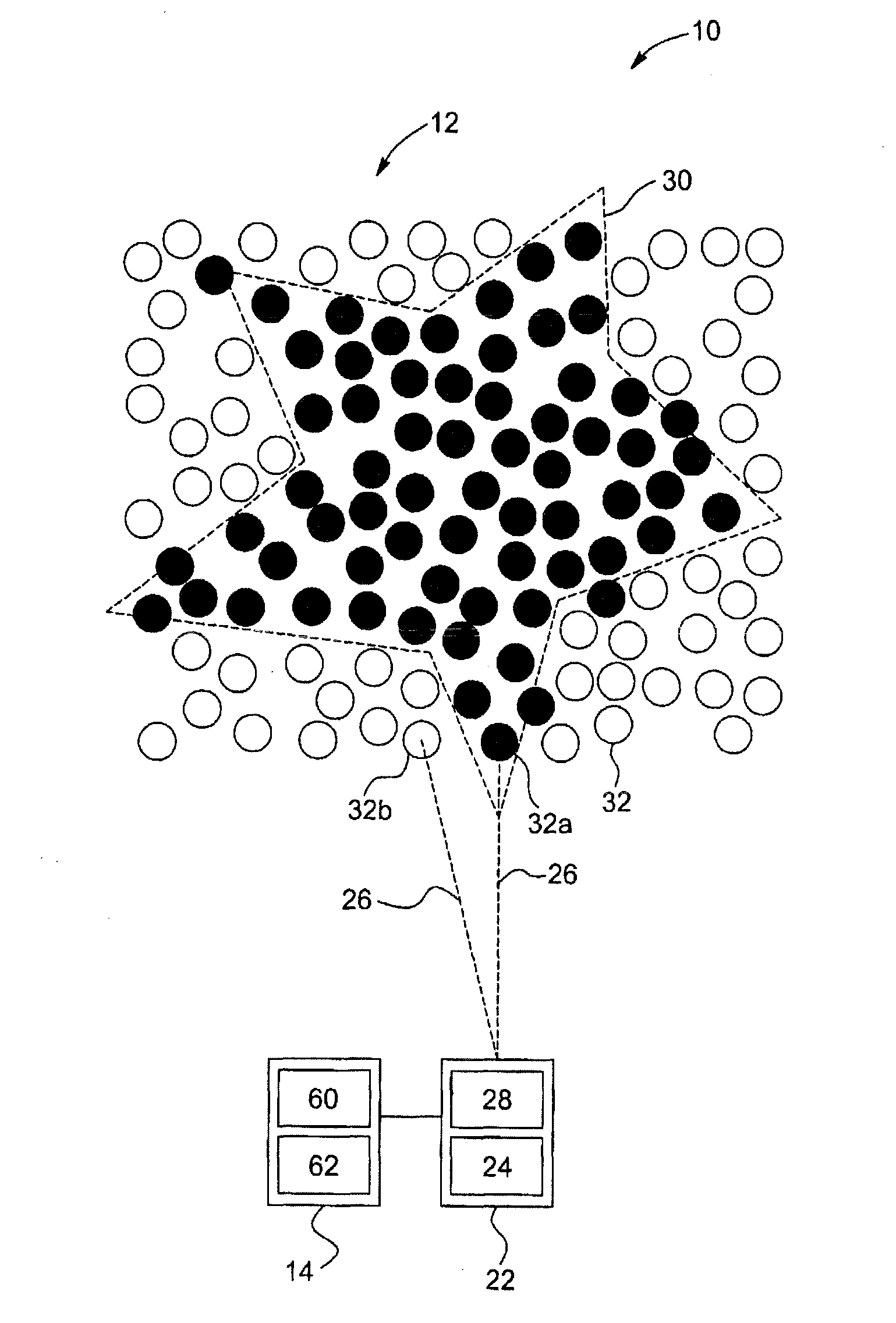
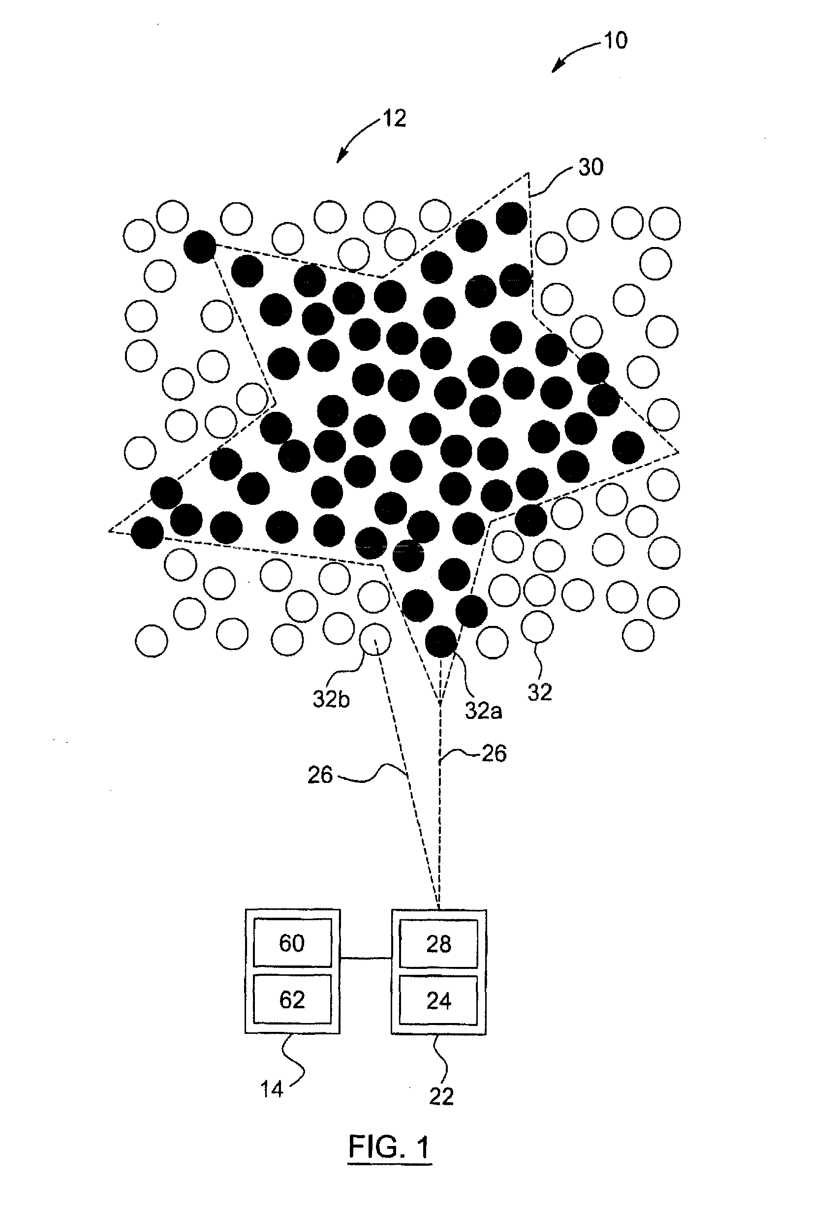
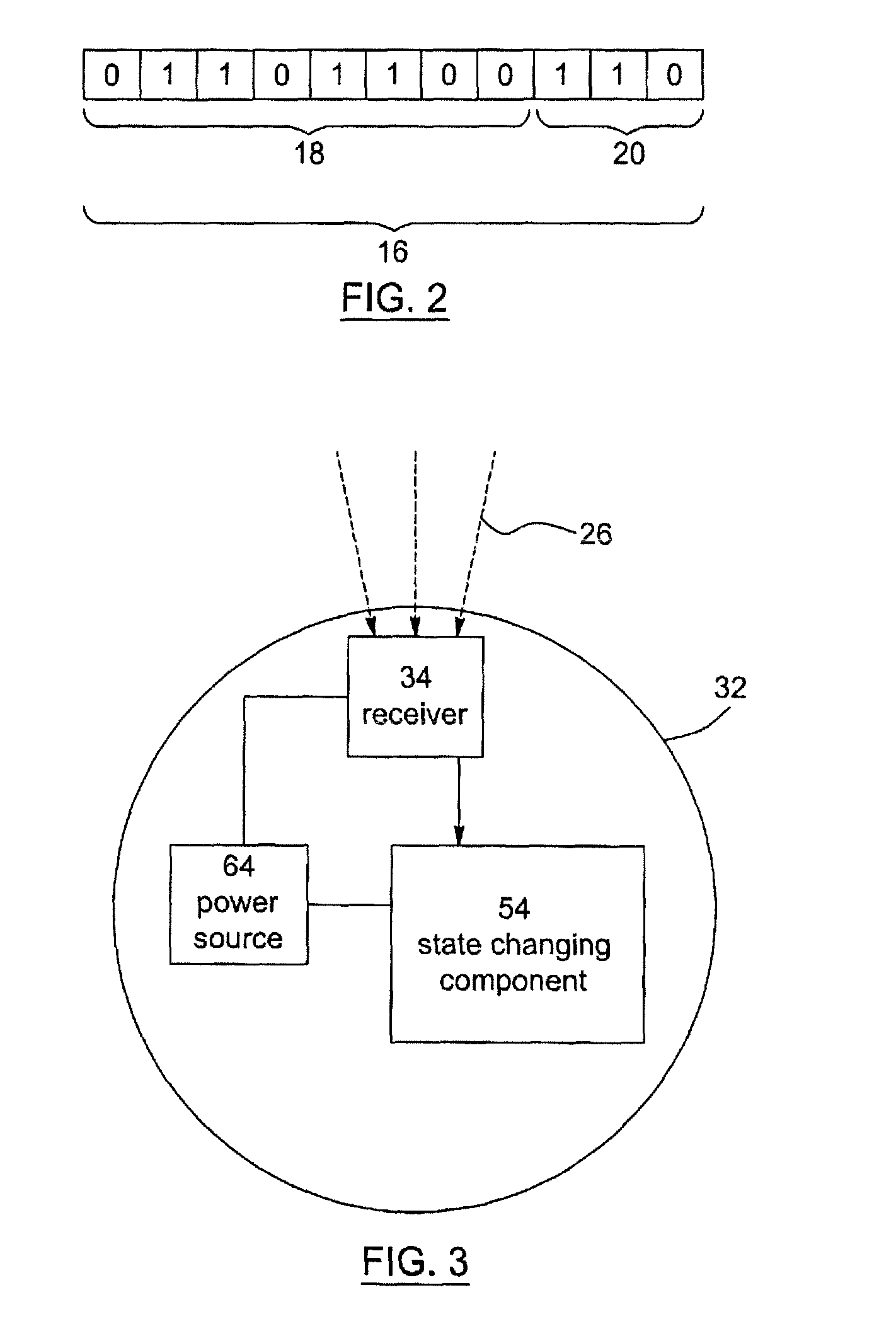
[0037]In accordance with a first aspect thereof, the present invention generally concerns a projecting system for creating am manifestation using a projector and several receiving units distributed within a given environment. Electromagnetic signals are sent by the projector and may vary in function of specific locations targeted by the projector. In other words, receiving units located within a target location of the environment will receive specific electromagnetic signals. These signals will include a state data, instructing the receiving element on a change of state they need to perform. The change of state can be for example a change of color. The combined effect of the receiving units will provide a manifestation, each unit display...


PUM


Abstract

The present invention concerns a projection system for providing a distributed manifestation within an environment. The projection system includes a data generator for generating a plurality of data sets of associated state data and spatial coordinate data. The projection system also includes a projector in communication with the data generator for receiving the data sets. The projector is provided with a signal generating module for generating a plurality of electromagnetic signals, and a projecting module for projecting each of the electromagnetic signals towards a target location within the environment. The projection system also includes a plurality of receiving units distributed within the environment, each receiving unit having a receiver for receiving one of the electromagnetic signals when the receiving unit is positioned in the corresponding target location, each receiving unit being adapted to perform a change of state in response to the state data.

Description

RELATED APPLICATIONS[0001]This application is a continuation of International Application No. PCT / CA2011 / 000700, filed Jun. 14, 2011, entitled “Devices And Methods For Providing A Distributed Manifestation In An Environment,” which claims priority to U.S. Provisional Application Ser. No. 61 / 449,290, filed Mar. 4, 2011, entitled “A Projecting System And A Projecting Method.” The entirety of each of the above applications is incorporated herein by reference.FIELD OF THE INVENTION[0002]The present invention generally relates to communication technologies. More specifically, the present invention concerns a projection system, a projector and a projection method for providing a distributed manifestation in an environment.BACKGROUND[0003]Projectors are used for a wide variety of applications, such as light shows or animations for music concerts and other live events, corporate presentations, video conferences, home theaters, etc. Typically, a video projector receives a video signal and pr...

Claims


Application Information

Patent Timeline
Patent Type & Authority Patents(United States)
IPC IPC(8): G03B21/00
CPCG06F3/1446H04N9/3194G06T3/005A63J5/02A63J25/00G03B21/2033H04N9/3155H05B47/155H05B47/195H04N5/7458H05B47/175
Inventor LECLERC, VINCENTKEROULAS, PATRICKDE BELLEVAL, VINCENT
Owner ESKI INC
Why Eureka
Try Eureka