
Method and apparatus for stretch blow molding a container

a container and container body technology, applied in the field of methods and apparatus for stretching blow molding containers, can solve the problems of cracking, shearing or other failure, weakened area susceptible to fracture, etc., and achieve the effects of reducing flexural stress, reducing drop impact failure, and improving drop impact or aesthetic characteristics

Inactive Publication Date: 2014-06-03
EASTMAN CHEM CO
View PDF36 Cites 0 Cited by
  • Summary
  • Abstract
  • Description
  • Claims
  • Application Information

AI Technical Summary

Benefits of technology

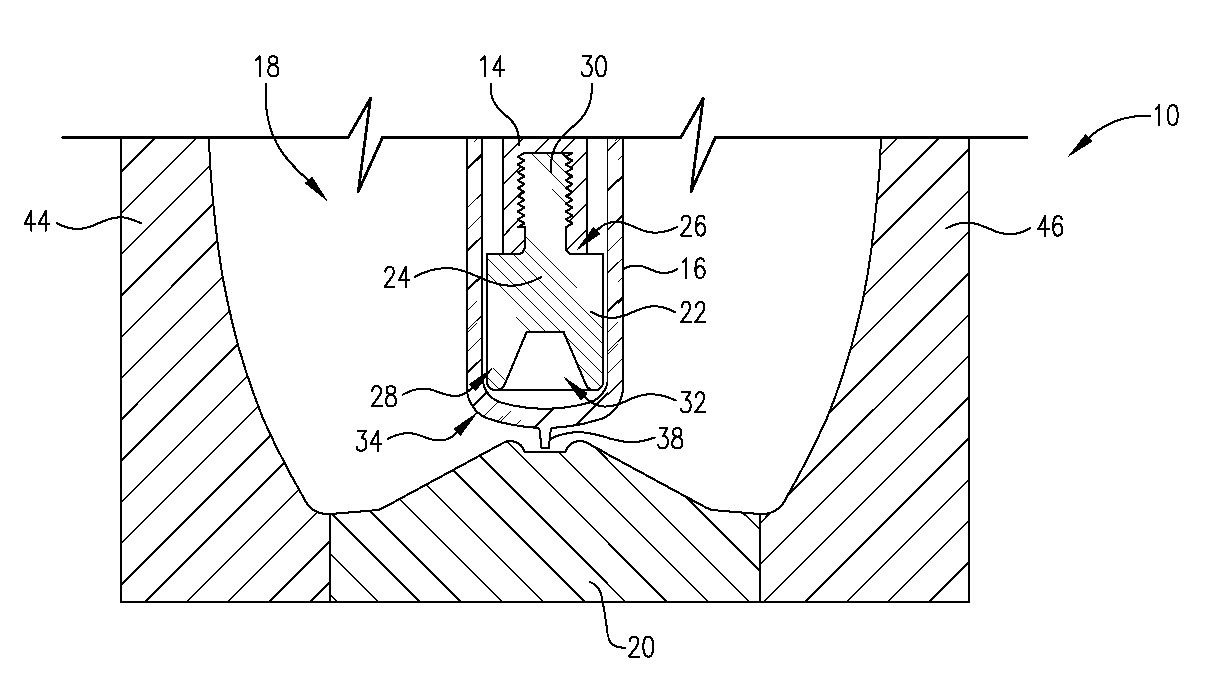
The present invention relates to a new method of blow molding containers that reduces the likelihood of drop impact failure. Unlike previous methods, the new method does not flatten or compress the sprue, which is a part of the molded container. Instead, the new method allows the sprue to remain relatively intact and positioned partially inside the container. This results in a flatter and stronger container bottom, which reduces the likelihood of the container being impacted from a drop. The new method can be used with different blow mold base shapes, providing better drop impact or aesthetic characteristics. In one example, simply adding a concave dome to the blow mold base does not provide the same benefits as the new method. The new method requires only a modification of the stretch rod tip, which is a relatively inexpensive and easier to retool.

Problems solved by technology

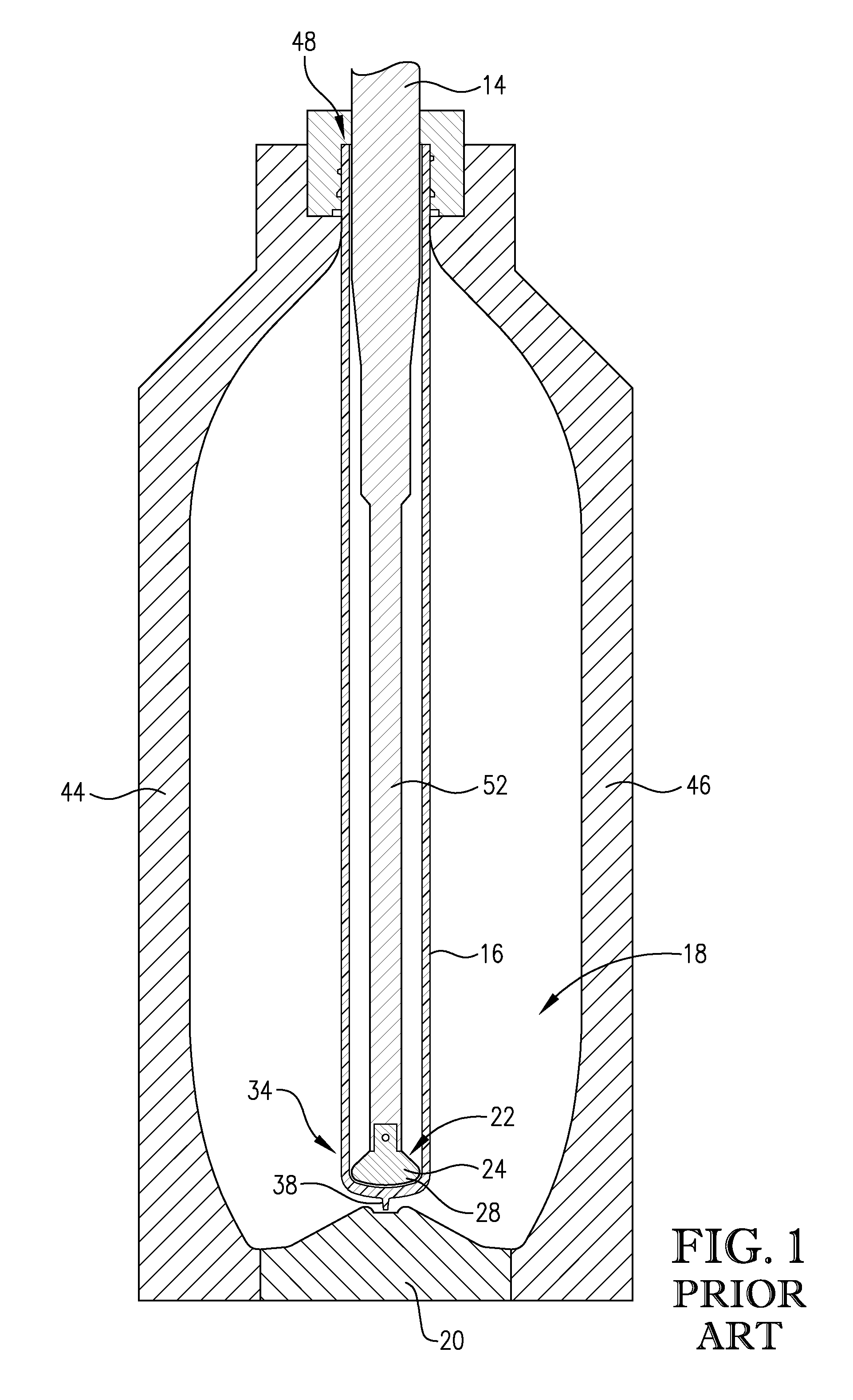
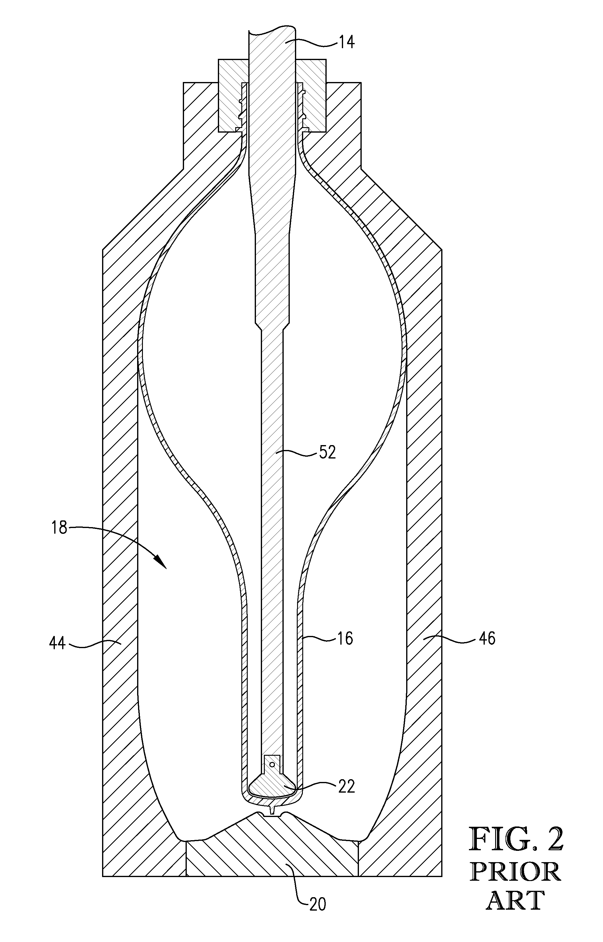
This method of accounting for the sprue 38 leaves a notch on an outside surface of the molded container that is aesthetically unpleasing, undesirably catches on clothing or other items, and presents a weakened area susceptible to fracture, cracking, shearing, or other failure during a drop impact.
However, after the container is fully molded, remnants of the sprue form a rough notch on the outside surface of the container.
As with ISBM, the notch presents a weakened area susceptible to fracture during a drop impact.

Method used


Image

  • Method and apparatus for stretch blow molding a container
  • Method and apparatus for stretch blow molding a container
  • Method and apparatus for stretch blow molding a container

Examples


examples

[0053]Applicant undertook testing of the hollowed tip of embodiments of the present invention on various container base shapes. All containers were molded bottles made from a preform comprising a copolyester containing 100 mole % terephthalic acid, 23 mole % 2,2,4,4-tetramethyl-1,3-cyclobutanediol and 77 mole % 1,4-cyclohexanedimethanol where the total mole % of dicarboxylic acid equals 100 mole % and the total mole % of glycols equals 100 mole %.

[0054]For Examples 1, 2 and 3, the formed bottles had a 355 ml nominal capacity, 45 g weight, and 28 mm finish. The bottles were formed on reheat blow equipment using 2 liter CSD style preforms. The sprues on each preform were trimmed to approximately 6.4 mm prior to stretch blow molding. Each of the stretch rod tips used was formed of stainless steel. For each example, bottles were formed using both the prior art stretch rod tip having a slightly rounded bottom (“Tip 1”) and the stretch rod tip of embodiments of the present invention havin...


PUM

PropertyMeasurementUnit
angleaaaaaaaaaa
angleaaaaaaaaaa
diameteraaaaaaaaaa

Abstract

An improved stretch rod tip having a hollowed area for receipt of a portion of a preform and at least a portion of a sprue during stretch blow molding of a container. Upon hardening of the container, the received portion of the preform becomes a protective dome over the received portion of the sprue that is at least partially internal to the container and that greatly reduces cracking, shearing, or other fracturing of the container due to a drop impact.

Description

RELATED APPLICATIONS[0001]This application claims the priority benefit of U.S. Provisional Patent Application Ser. No. 61 / 302,318, filed Feb. 8, 2010.BACKGROUND[0002]1. Field of the Invention[0003]Embodiments of the present invention are generally directed to a method and apparatus for stretch blow molding a container, such as a bottle. More particularly, embodiments of the present invention are directed to a tip for a stretch rod used during stretch blow molding that provides improved drop impact characteristics for the molded container.[0004]2. Description of the Related Art[0005]Stretch blow molding of containers generally comprises a first step of injection molding a preform made of a heat-softened amorphous polymer or other suitable material, and a second step of stretching and blowing the preform in a blow mold to form the final container. FIGS. 1-3 illustrate an exemplary blow mold 18 comprising a blow mold base 20 and left and right sides 44,46. As is known in the art, the b...

Claims


Application Information

Patent Timeline
Patent Type & Authority Patents(United States)
IPC IPC(8): B29C49/12
CPCB29B2911/1404B29B2911/1402B29K2081/06B29B2911/14666B29B2911/14466B29K2023/12B29B11/14B29K2025/00B29B2911/14493B29C2791/007B29C49/06B29B2911/14033B29B2911/14106B29C2049/1238B29B2911/14026B29B2911/1498B29K2067/00B29B11/08B29K2069/00B29L2031/7158B29B2911/14133B29B2911/1444B29K2105/258B29C49/12B29B2911/14486B29C2949/26B29C2949/24B29C2949/28B29C2949/22B29C2949/3024B29C2949/3032B29C2949/0781B29C2949/078B29C2949/0777B29C2949/0773B29C2949/0822B29C2949/0872B29C49/1215B29C49/071B29C2949/0715
Inventor MCCRARY, ROBERT, ELLIS
Owner EASTMAN CHEM CO
Learn More