Heating appliance covered with a self-cleaning coating and production method thereof
a self-cleaning, heating appliance technology, applied in the direction of heating apparatus, furniture, applications, etc., can solve the problems of affecting the appearance of the sole plate, the loss of the least partial glide quality, and the difficulty of ironing
- Summary
- Abstract
- Description
- Claims
- Application Information
AI Technical Summary
Benefits of technology
Problems solved by technology
Method used
Image
Examples
example 1
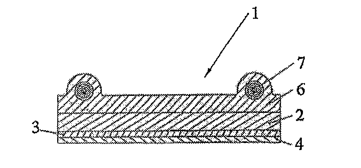
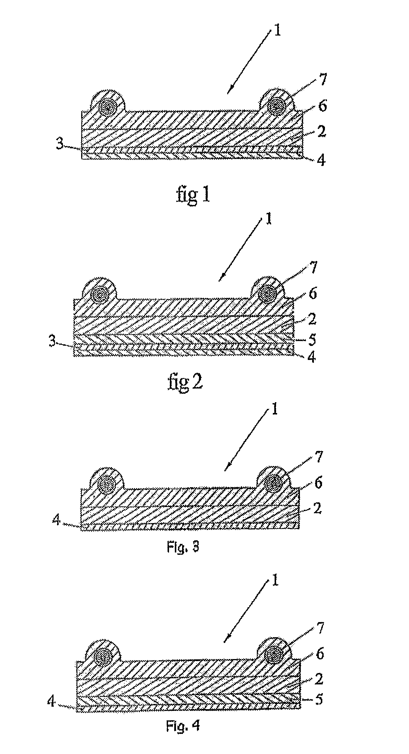
1st Example of PdO / CeO2 Bilayer Coating According to the Invention on an Enameled Support
[0120]A clean iron sole plate made of enameled aluminum is placed on a thick support made of aluminum acting as heat reservoir in order to limit, as far as possible, the variations in temperature.
[0121]The assembly is heated in an oven to a temperature of 300° C. The sole plate, with the support, is placed under infrared radiation for a few seconds until a surface temperature of between 300° C. and 350° C. is achieved.
[0122]Cerium nitrate is dissolved in water. This cerium nitrate solution is subsequently sprayed over the sole plate using an air gun. A layer with a thickness of approximately 50 nm to 100 nm, measured according to the RBS method, is then deposited.
[0123]After the application of this internal layer, the sole plate is heated in the oven to 250° C. and then placed under infrared radiation at a temperature of between 280° C. and 350° C. for a few seconds.
[0124]An aqueous palladium ni...
example 2
2nd Example of PdO / Y2O3 Bilayer Coating According to the Invention on an Enameled Support
[0130]A clean iron sole plate made of enameled aluminum is placed on a thick support made of aluminum acting as heat reservoir in order to limit, as far as possible, the variations in temperature. The assembly is heated in an oven to a temperature of 300° C. The sole plate, with the support, is placed under infrared radiation for a few seconds until a surface temperature of between 300° C. and 350° C. is achieved.
[0131]Yttrium nitrate is dissolved in water. This yttrium nitrate solution is subsequently sprayed over the sole plate using an air gun. A layer with a thickness of approximately 50 nm to 100 nm, measured according to the RBS method, is then deposited.
[0132]After the application of this internal layer, the sole plate is heated in the oven to 250° C. and then placed under infrared radiation at a temperature of between 280° C. and 350° C. for a few seconds.
[0133]An aqueous palladium nitra...
example 3
Example of a Monolayer Coating (PdO+Y2O3) According to the Invention on an Enameled Support
[0139]A clean iron sole plate made of an enameled aluminum is placed on a thick support made of aluminum acting as heat reservoir in order to limit, as far as possible, the variations in temperature.
[0140]The assembly is heated in an oven to a temperature of 250° C. The sole plate, with the support, is placed under infrared radiation for a few seconds until a surface temperature of between 280° C. and 350° C. is achieved.
[0141]An aqueous palladium nitrate solution stabilized by nitric acid, to which yttrium nitrate is added as dopant, is sprayed over the sole plate using an air gun. A layer with a thickness of approximately 50 to 100 nm, measured according to the RBS method described above, is then deposited.
[0142]After application of this external layer, the assembly is rebaked under infrared radiation at a temperature of 500° C. for 4 minutes.
[0143]An iron sole plate is obtained, the self-cl...
PUM
| Property | Measurement | Unit |
|---|---|---|
| Temperature | aaaaa | aaaaa |
| Temperature | aaaaa | aaaaa |
| Temperature | aaaaa | aaaaa |
Abstract
Description
Claims
Application Information
 - R&D
- Intellectual Property
- Life Sciences
- Materials
- Tech Scout
- Unparalleled Data Quality
- Higher Quality Content
- 60% Fewer Hallucinations
Browse by: Latest US Patents, China's latest patents, Technical Efficacy Thesaurus, Application Domain, Technology Topic, Popular Technical Reports.
© 2025 PatSnap. All rights reserved.Legal|Privacy policy|Modern Slavery Act Transparency Statement|Sitemap|About US| Contact US: help@patsnap.com


