Drive unit with overload protection for driving a ring gear

a technology of ring gear and drive unit, which is applied in the direction of gearing, ways, hoisting equipment, etc., can solve the problems of enormous capital damage, inability to offer overload protection, and inability to guarantee overload protection

Active Publication Date: 2014-06-10
LIEBHERR COMPONENTS BIBERACH GMBH
View PDF27 Cites 10 Cited by
  • Summary
  • Abstract
  • Description
  • Claims
  • Application Information

AI Technical Summary

Benefits of technology

[0007]Due to the inventive arrangement of the overload protection between the transmission and the pinion, a torque flow from the output shaft to the drive motor can still be monitored, even if the transmission is blocked. The overload protection in accordance with the invention thus provides for protecting the teeth of the ring gear or the pinion against a tooth overload fracture in the case of the failure of the transmission. The overload protection is disposed behind all transmission components, so that in the case of a blockage of the transmission the overload protection ensures that with a torque flow from the ring gear to the pinion the teeth can be protected against tooth overload fracture. Known drive units cannot offer such protection of the teeth of the ring gear, so that enormous capital damages can occur as a result of tooth fracture damages.
[0029]The ring gear likewise can serve for driving a winch. In particular, in winches with external ring gear, which are driven by one or more drive units, the ring gear thus can be protected against tooth fracture. Here as well, the drive units of the invention advantageously are used when two or more drive units together are employed for driving a ring gear.

Problems solved by technology

With known drive units, however, an optimum overload protection cannot be guaranteed.
Known drive units cannot offer such protection of the teeth of the ring gear, so that enormous capital damages can occur as a result of tooth fracture damages.

Method used


Image

  • Drive unit with overload protection for driving a ring gear
  • Drive unit with overload protection for driving a ring gear
  • Drive unit with overload protection for driving a ring gear

Examples


Embodiment Construction

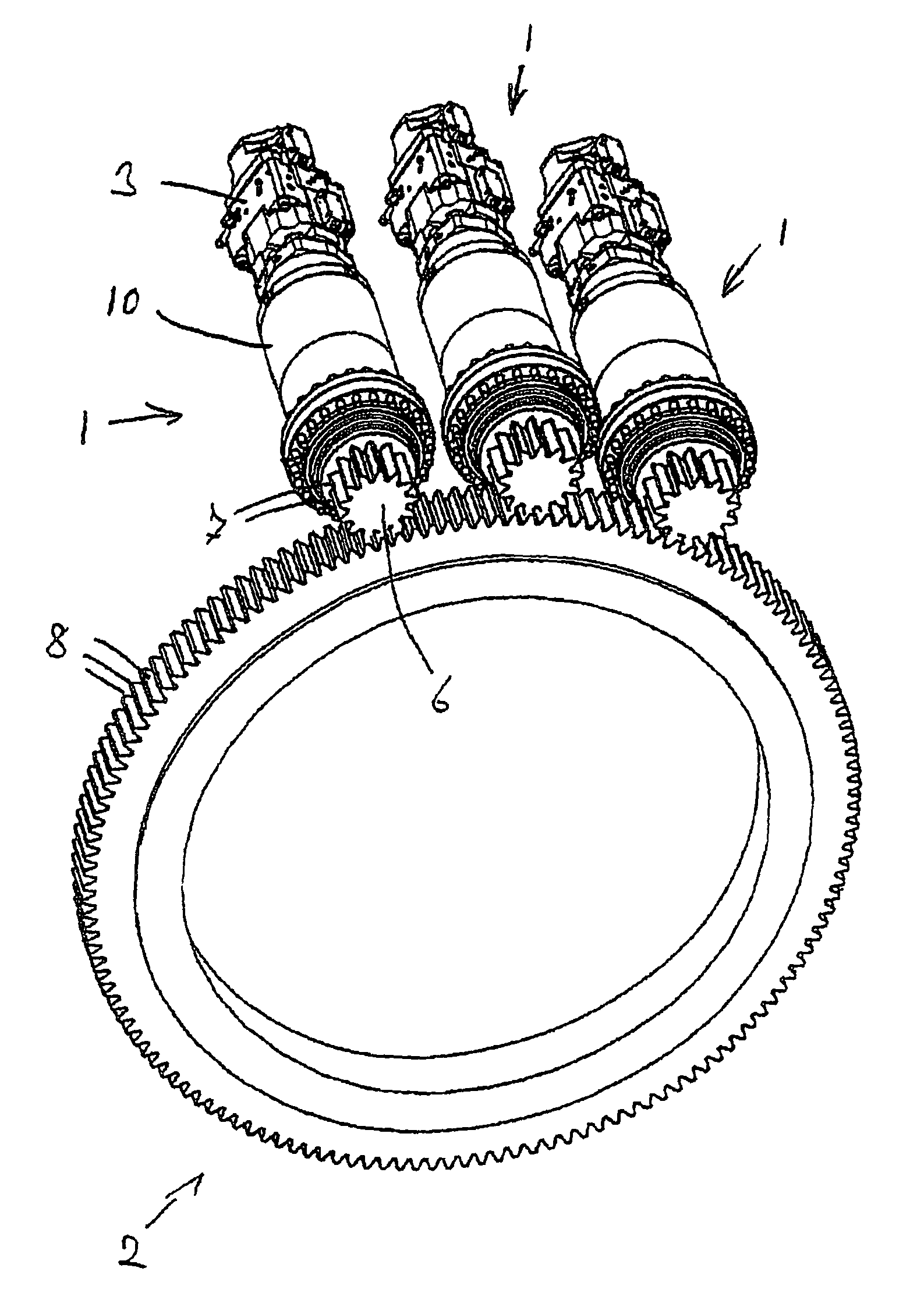
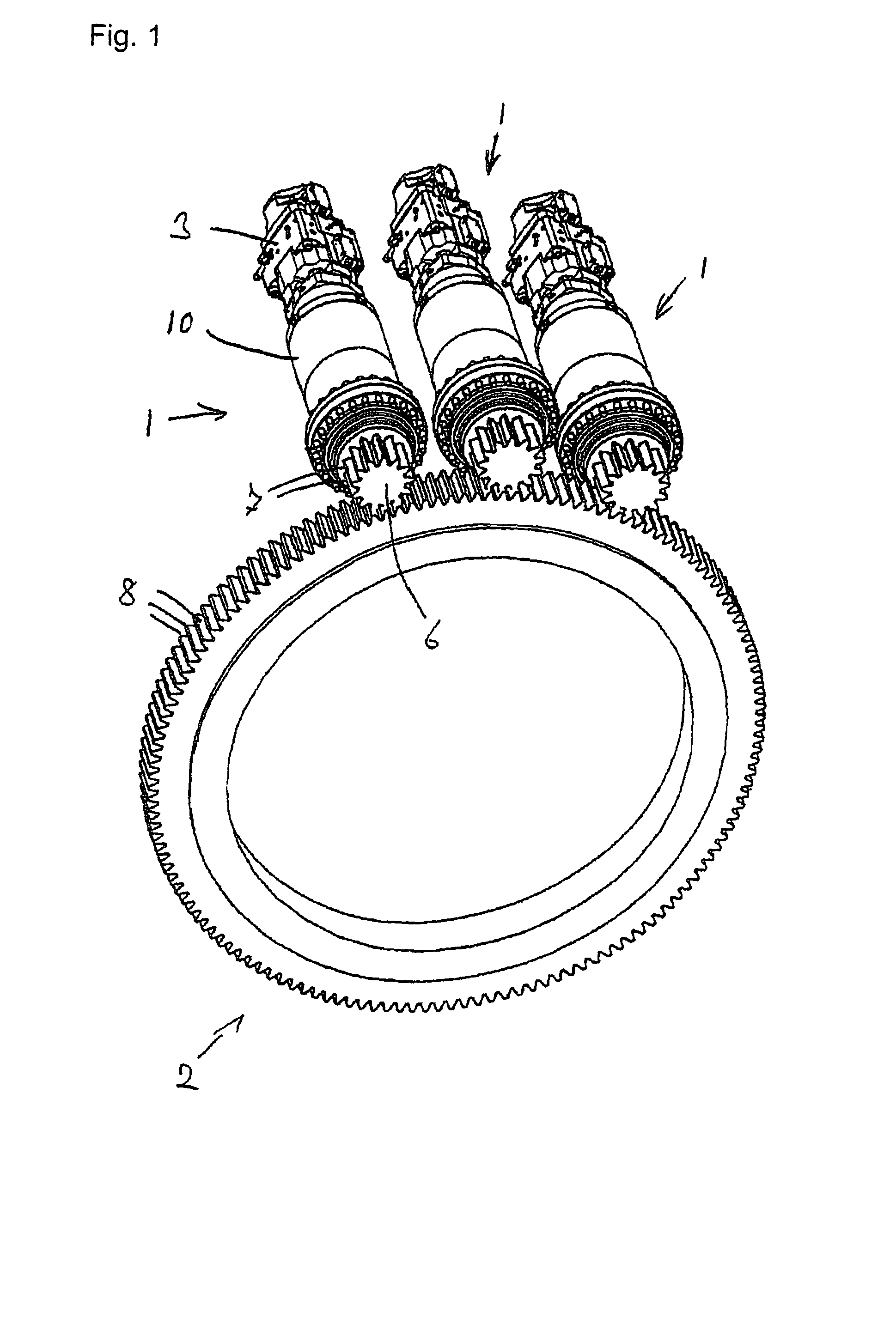
[0039]FIG. 1 shows an embodiment of a device in accordance with the invention. There is provided a plurality of drive units 1 in accordance with the invention, which together drive a ring gear 2. Each of the drive units 1 includes a motor 3, in this embodiment a hydraulic motor. Alternatively, other motors, in particular electric motors, might also be used. Each of the drive units furthermore includes a transmission and an output shaft, which are mounted in the common housing 10. On the output shaft a pinion 6 each is arranged, which meshes with the ring gear 2. The teeth 7 of the pinions 6 are in connection with the teeth 8 of the ring gear. The drive units 1 can be mounted on the device via a mounting flange. The ring gear 2 is of ring-shaped design and includes teeth 8 on its outside. The ring gear also can include an internal toothing.

[0040]In the embodiment shown in FIG. 1, three drive units are provided for the ring gear 2. Alternatively, however, only one or two drive units m...


PUM


Abstract

A drive unit for driving a ring gear includes a motor, a transmission and a drive shaft, on which a pinion is arranged for driving the ring gear, wherein the drive unit includes a mechanical overload protection. In accordance with the invention the overload protection is arranged between the transmission and the pinion.

Description

BACKGROUND OF THE INVENTION[0001]The present invention relates to a drive unit for driving or braking a ring gear, comprising a motor or a brake, a transmission and an output shaft on which a pinion is arranged for driving the ring gear.[0002]Such drive units are used for example for driving slewing or swing gears, in particular for driving a slewing gear of a wind turbine or for driving a slewing or swing gear of a crane or an excavator. The ring gear has teeth on its outer circumference or inner circumference, which mesh with the teeth of the pinion. By driving the pinion via the output shaft, the ring gear thus can be driven. Ring gears are also used for driving winches, in particular for driving winches of a crane.[0003]For driving a ring gear, a plurality of drive units can also be used in parallel, when great drive forces are required.[0004]For such drive units, overload protection devices, e.g. in the form of slip clutches or predetermined breaking points, are known already, ...

Claims


Application Information

Patent Timeline
Patent Type & Authority Patents(United States)
IPC IPC(8): F16D7/04F16D7/02F16D9/08F16H35/10F16D9/06
CPCF16D7/08B66C23/86E02F9/123F03D11/00F16D7/044B66D1/58E02F9/128F16H35/10F16D9/08Y02E10/722F16H2035/103B66D1/14F03D80/00Y10T74/19684Y10T74/19614Y10T74/19847Y02E10/72F16B2200/63
Inventor HAUSLADEN, NORBERTSEDLMAIER, MATTHIAS
Owner LIEBHERR COMPONENTS BIBERACH GMBH
Why Eureka
Try Eureka