Portable various pitch rope tow system

Inactive Publication Date: 2014-06-10
NIEDERMEYER LEON E
View PDF3 Cites 13 Cited by
  • Summary
  • Abstract
  • Description
  • Claims
  • Application Information

AI Technical Summary

Problems solved by technology

The problem with is system is that there is no way to extend the line to more than one post as there is no simple way for the tow bar from pass from post to post.
Another problem with these te

Method used


Image

  • Portable various pitch rope tow system
  • Portable various pitch rope tow system
  • Portable various pitch rope tow system

Examples


Embodiment Construction

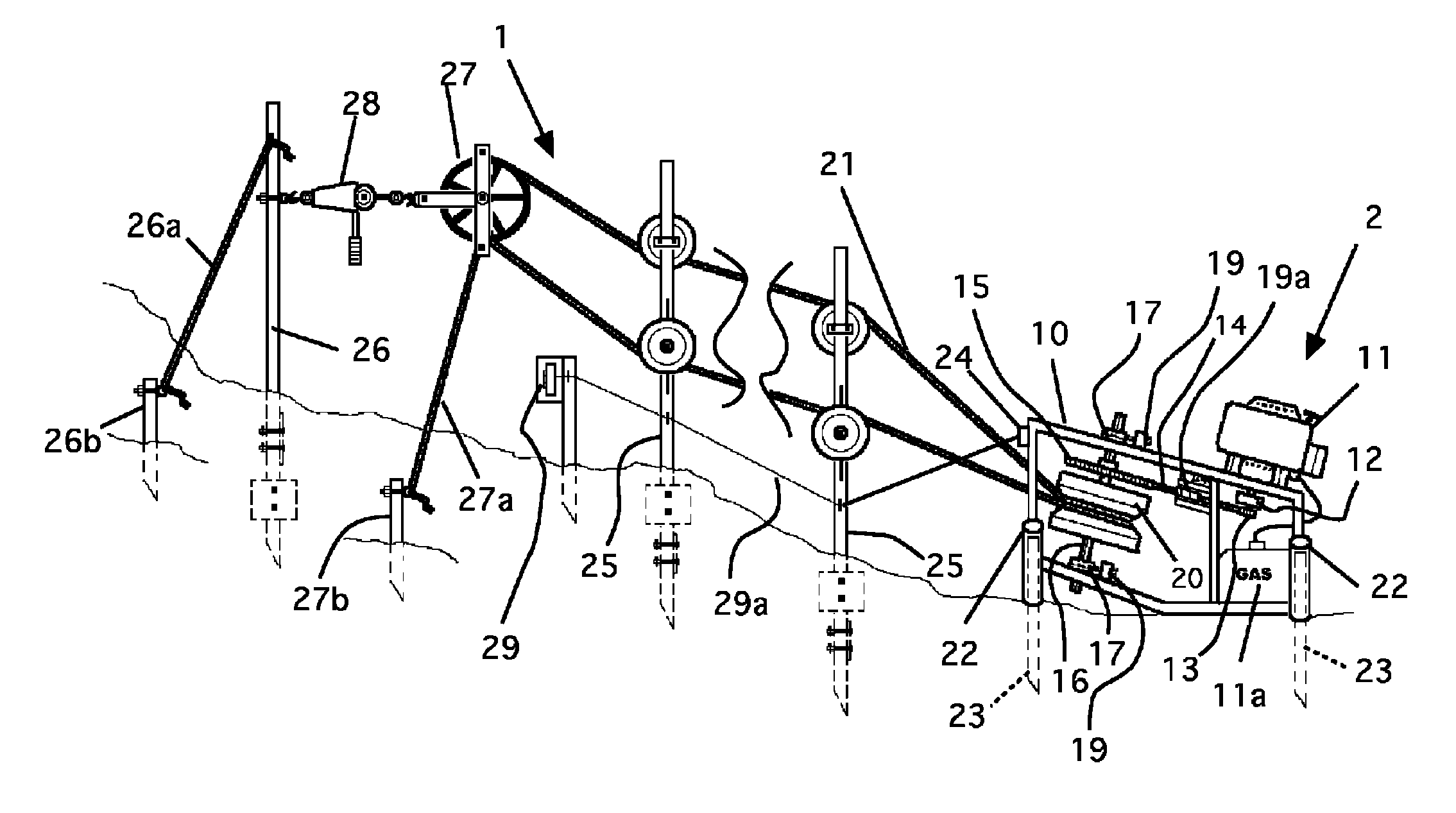
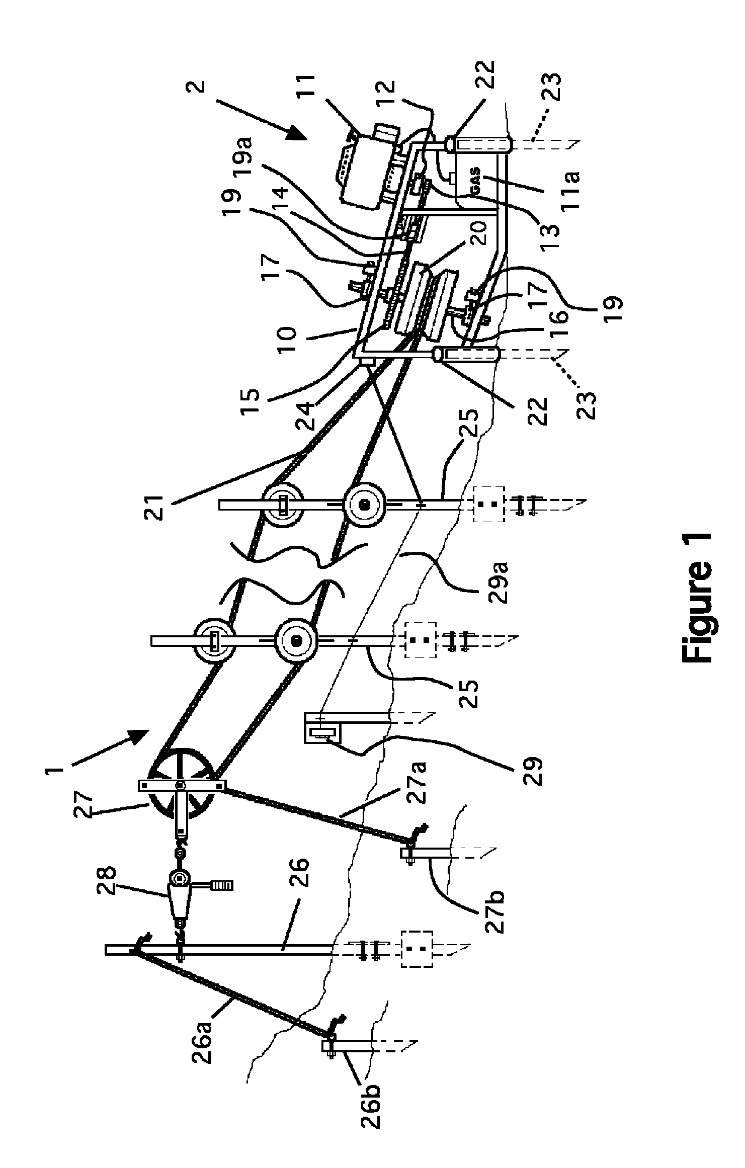
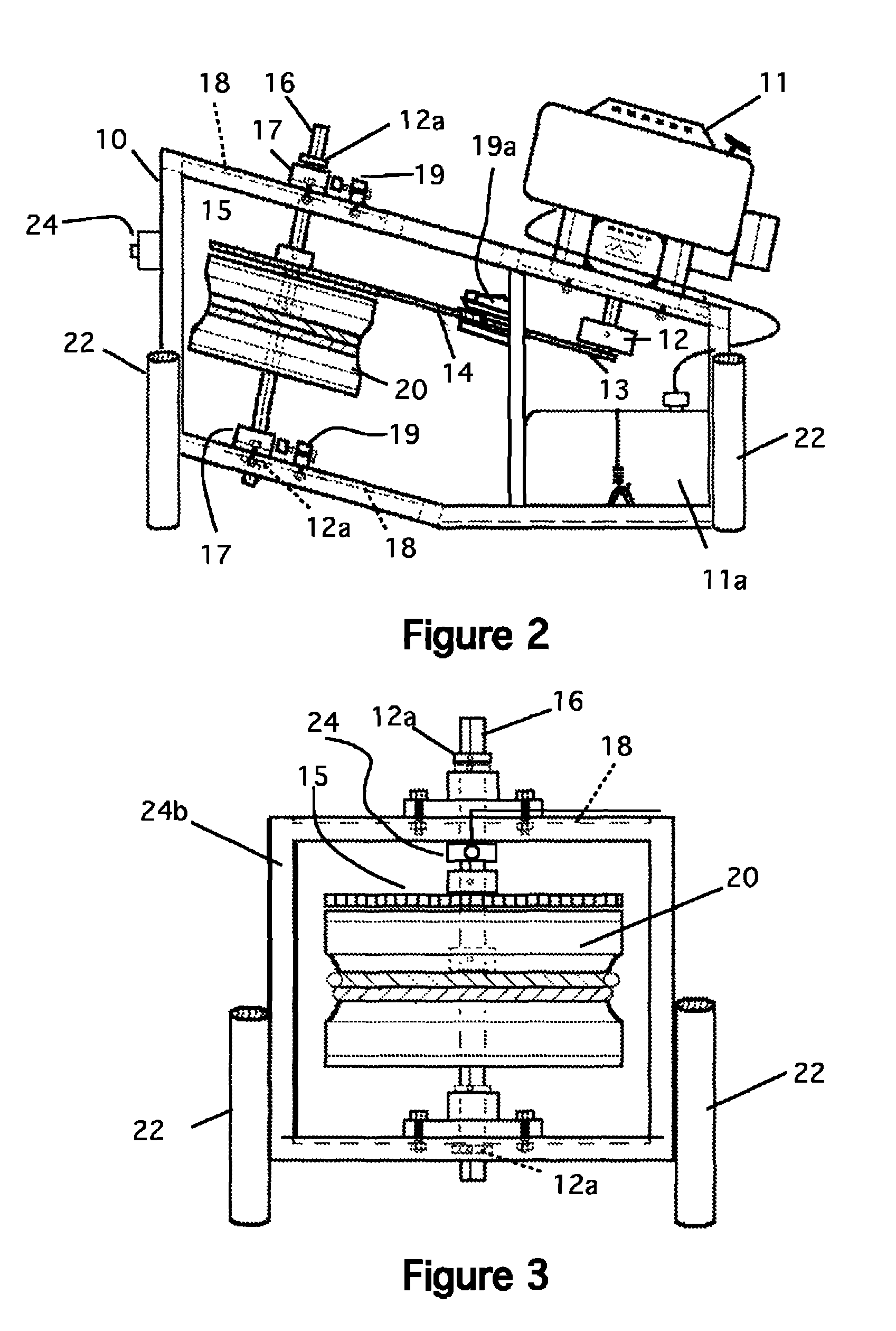
[0026]Referring now to FIG. 1, a side view of the system 1 is shown. The system has a number of components. First, there is a main drive unit 2 that consists of an aluminum mainframe 10, which supports a gas powered, air-cooled, vertical drive shaft engine 11. The engine is supplied from a gas tank, 11a, which is mounted in the bottom of the frame 10. Of course, any similar type of engine or motor can be used. Gas is preferred as a fuel because the invention is preferably used in remote areas as a temporary ski tow in areas in which electricity is not normally available. A centrifugal clutch 12 is attached to the drive shaft of the engine 11 (see FIG. 2). A sprocket 13, which allows load free starting from the clutch, runs a chain 14. The chain 14 is attached to a keyed hub sprocket 15, which runs a keyed drive shaft 16 (see FIG. 2). The drive shaft 16 has top and bottom flange block bearings 17. The bearings and drive shaft are mounted on plates 18 with slotted holes to adjust chai...


PUM


Abstract

A portable ski rope tow system, which is capable of ascending various pitched slopes. The system only needs to be anchored into snow for operation. The system consists of a main drive mechanism, a continuous loop tow rope, rope support posts that include adjustable rope guide sheave wheels, an end post that includes a rope return pulley utilizing a cable puller/come-a-long for tow rope tensioning. The system is equipped with a pull cord safety device, which runs the length of the system. A towrope clamp attached to a climbing harness is needed by the skier/snowboarder to eliminate hand fatigue and mainly to be able to pass through rope guide sheave wheels. Most of the structural components of the system are lightweight, made of aluminum to provide easier mobility, set up and take down.

Description

CROSS REFERENCE TO RELATED APPLICATIONS[0001]This application claims benefit of Provisional application 61 / 447,234 filed Feb. 28, 2011STATEMENT REGARDING FEDERALLY SPONSORED RESEARCH AND DEVELOPMENT[0002]Not ApplicableBACKGROUND OF THE INVENTION[0003]1. Field of the Invention[0004]This invention relates to ski rope tow system and particularly to portable ski rope tow systems, which are capable of ascending various pitched slopes.[0005]2. Description of the Prior Art[0006]Today, ski facilities uses two main systems for moving skiers to the top of a ski run. The first is the chair lift and the second is the towline. Towlines have been in use longer than chair lifts as they are much easier to install. At traditional ski areas, these lifts are usually permanently installed. That means setting poles or supports in the ground at specific places and installing all of the necessary equipment needed to operate them.[0007]Alternatively, temporary towlines may be installed at locations. These ...

Claims


Application Information

Patent Timeline
IPC IPC(8): B61B7/00
CPCB61B7/00B61B7/02
Inventor NIEDERMEYER, LEON, E.
Owner NIEDERMEYER LEON E
Why Eureka
Try Eureka