
System for integrating electronic monitors into a room decor

a technology for electronic monitors and room decor, applied in television systems, door/window protective devices, transportation and packaging, etc., can solve the problems of particle pollution, affecting the quality of projected images, and affecting the appearance of the room,

Active Publication Date: 2014-06-10
HEALY JR JAMES E +1
View PDF15 Cites 1 Cited by
  • Summary
  • Abstract
  • Description
  • Claims
  • Application Information

AI Technical Summary

Benefits of technology

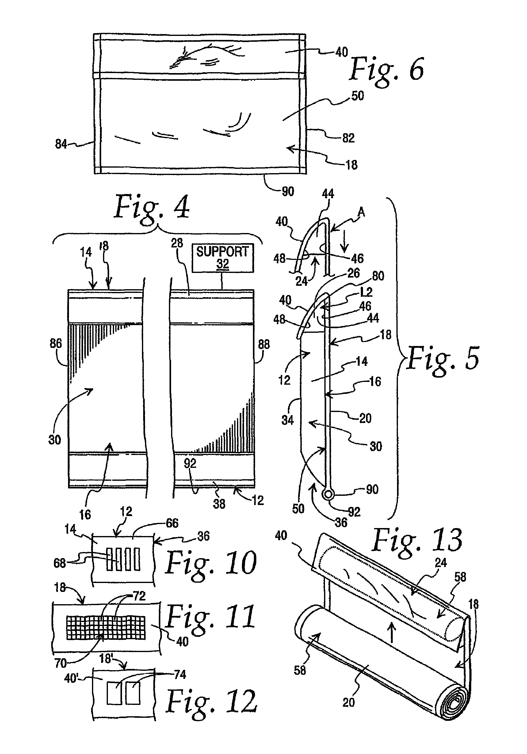
[0024]In one form, the cover assembly incorporates an elastic material that allows a fore-and-aft dimension of the pocket to be varied to thereby accommodate monitors with different fore-and-aft dimensions.

Problems solved by technology

However, when the monitors are not in use, they are equally dramatic in terms of dominating large areas of rooms in which they reside.
First of all, the monitors not only act as receptacles for dust, but tend to attract dust particles.
Heated plastic components having exposed surfaces commonly become electrically charged, as a result of which they tend to draw and cause the adherence of dust particles.
The attraction of dust particles creates aesthetic and potentially operational problems.
Repeated cleaning, particularly of the monitor surface through which images are seen, may cause scratching and eventually detract from the quality of the projected image.
Significant accumulation of particles upon working components may lead to overheating and eventually component failure.
This latter condition is aggravated by manual dust removal that often causes the inadvertent direction of particles through the vent openings to within the housing.
As noted above, another significant drawback with large monitors, be they wall or table mounted, is that they often visually dominate portions, or the entirety of, a wall or room.
The monitors may thus significantly detract from the décor in a room that may have been designed with a carefully selected theme or style that is not compatible with the presence of the monitors.
The structure in Maxson requires a fairly elaborate mounting system that may be quite expensive and also take up a significant amount of space in addition to that occupied by the monitor itself.
Maxson's structure does not appear to be configured to protect, particularly the vent region of the monitors, from dust accumulation and, in fact, may complicate access to this and other areas for cleaning and creates additional contours that must be accessed, potentially inconveniently, to extract dust.
Further, in the event that the front component is not repositioned after monitor use to cover the same, it represents an obtrusive frontal projection that potentially is more visually offensive than the monitor alone.
It is also known to provide relatively expensive cabinetry to define a receptacle for a monitor.
While this approach does eliminate much of the dust accumulation problem, it generally will involve a significant expense and structure that potentially becomes dominant to the eye to the point that it performs counterproductively in terms of hiding the presence of the monitor when not in use.
In spite of the long-recognized desirability of protecting and integrating monitors into a room décor, the inventor herein knows of no commercial options that are feasible.
Otherwise, the system is likely not to be employed or to be left in a single state which may ultimately defeat its purpose.
Further, ideally the system would not add appreciably to the space occupied by the monitor itself.
Many of the above design objectives compete with each other and it is believed that this may have contributed to the fact that no viable systems have been devised for commercial use to this date.

Method used


Image

  • System for integrating electronic monitors into a room decor
  • System for integrating electronic monitors into a room decor
  • System for integrating electronic monitors into a room decor

Examples


Embodiment Construction

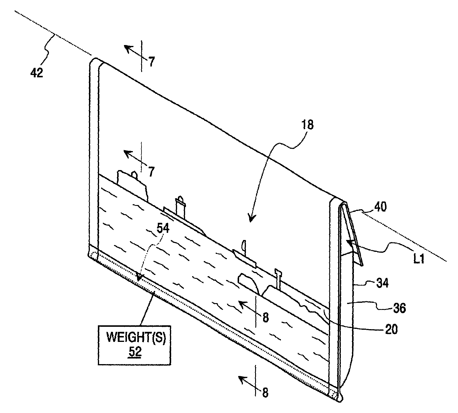
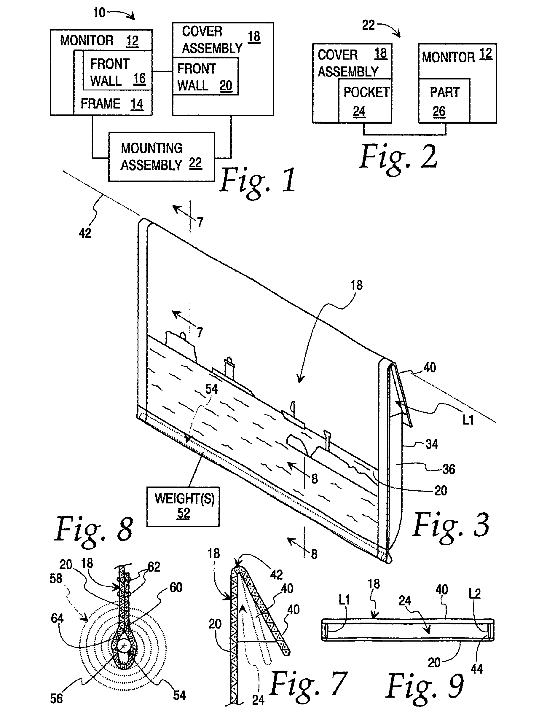
[0056]Referring initially to FIG. 1, a schematic representation of a monitor system, according to the present invention, is shown at 10. The monitor system 10 consists of a monitor 12 for an electronic device. The electronic device may be a television or a computer with which the monitor 12 is associated. The monitor 12 has a frame 14 and a substantially flat, front wall 16 at which an image is projected.

[0057]A cover assembly 18 has an opaque front wall 20 that is configured to block the front wall 16 of the monitor 12 with the cover assembly 18 operatively engaged with the monitor 12.

[0058]A mounting assembly 22 functions to allow the cover assembly 18 to be changed between a first state, wherein the cover assembly 18 is fully separated from the monitor 12, and a second state, wherein the cover assembly 18 is operatively engaged with the monitor 12.

[0059]The mounting assembly 22 may be on the monitor 12 alone, the cover assembly 18 alone, or consist of components on each of the mo...


PUM


Abstract

A monitor system having: a) a monitor for an electronic device with a frame and a substantially flat front wall, at which an image is projected; and b) a cover assembly with a front wall that is configured to block the flat front wall of the monitor with the cover assembly operatively engaged with the monitor. The cover assembly further has a mounting assembly that allows the cover assembly to be changed between: i) a first state wherein the cover assembly is fully separated from the monitor; and ii) a second state wherein the cover assembly is operatively engaged with the monitor. The mounting assembly has a pocket that opens in a first direction. The pocket is movable in the first direction relative to the monitor from a separated, pre-assembly position to cause a first part of the monitor to be seated in the pocket with the cover assembly in the second state.

Description

BACKGROUND OF THE INVENTION[0001]1. Field of the Invention[0002]This invention relates to electronic monitors, such as those used on computers and televisions and, more particularly, to a system for strategically covering the monitors to integrate them into the décor of a room in which they reside.[0003]2. Background Art[0004]The proliferation of computers and flat screen televisions has led to the placement of a multitude of monitors throughout residences and businesses. It is not uncommon to see multiple monitors in a single room, as in home offices, bedrooms, living rooms, etc.[0005]Developing technology has allowed monitors to be made with a minimal depth and with a square front that consists of the projection area with but a modest width of frame therearound. This structural compaction has allowed users to select large monitors without having to contend with obtrusive cabinetry that was typical of earlier tube technology.[0006]Current monitor design lends itself to different ty...

Claims


Application Information

Patent Timeline
Patent Type & Authority Patents(United States)
IPC IPC(8): B65D65/02
CPCH04N5/64
Inventor HEALY, JR., JAMES E.HEALY, SUSAN F.
Owner HEALY JR JAMES E
Learn More