Sharps container with blade remover, needle unsheather, latch and security alignment extensions

a technology for scalpel handles and containers, applied in the direction of manufacturing tools, incision instruments, transportation and packaging, etc., can solve the problems of affecting the safety of blades, so as to achieve easy and effective sealing and low cost

Active Publication Date: 2014-06-17
HOFTMAN MOSHE MIKE
View PDF15 Cites 15 Cited by
  • Summary
  • Abstract
  • Description
  • Claims
  • Application Information

AI Technical Summary

Benefits of technology

[0016]This disposable sharps container is a unitary, low cost plastic case which sits flat on any surface. Once all the blades have been removed and placed in the sharps container, the s

Problems solved by technology

During surgery, some of the disposable blades may get dull or become contaminated and must be replaced by new sharp, sterile blades.
Such bending and sliding of the blade is dangerous because it may cut the nurse.
The blade may then be lost temporarily.
However, this surgical blade removal and disposal device suffers from a number of drawbacks.
Third, al

Method used


Image

  • Sharps container with blade remover, needle unsheather, latch and security alignment extensions
  • Sharps container with blade remover, needle unsheather, latch and security alignment extensions
  • Sharps container with blade remover, needle unsheather, latch and security alignment extensions

Examples


Embodiment Construction

[0064]The invention is now discussed with reference to the figures.

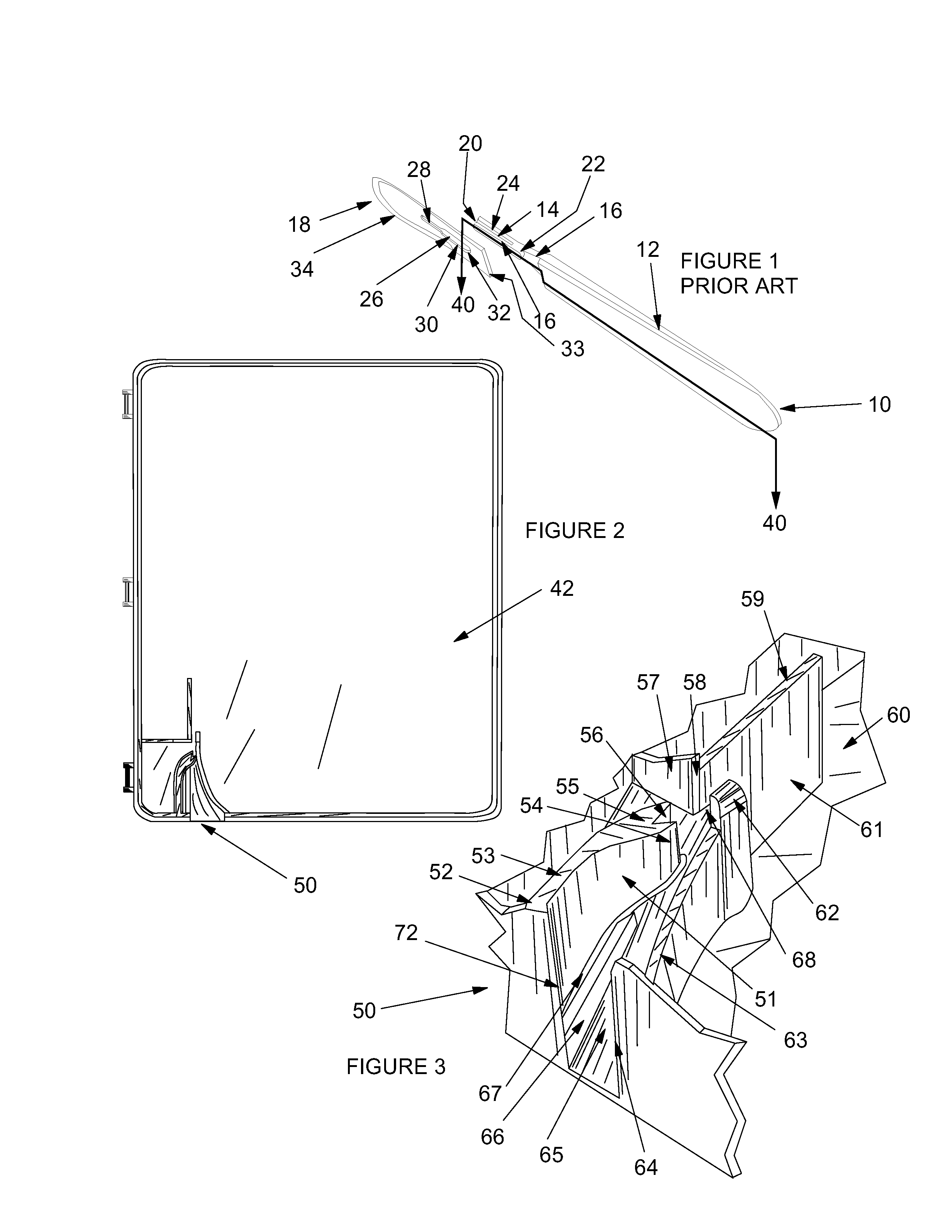
[0065]FIG. 1 shows, as described above, a prior art scalpel handle 12 and blade 18. Section 40 runs along a bottom edge of handle 12 and a mid section of inserted portion 14 and neck portion 16. In FIGS. 8 and 9, section 40 will permit viewing of the operation of the invention blade remover.

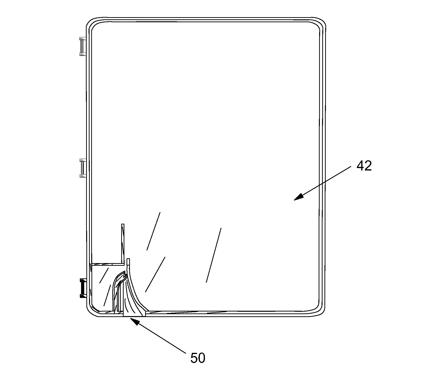
[0066]FIG. 2 shows a top view of a disposable sharps container 42 with the invention blade remover 50. The blade remover 50 will now be discussed with reference to FIGS. 3 through 7 that show several aspects of blade remover 50.

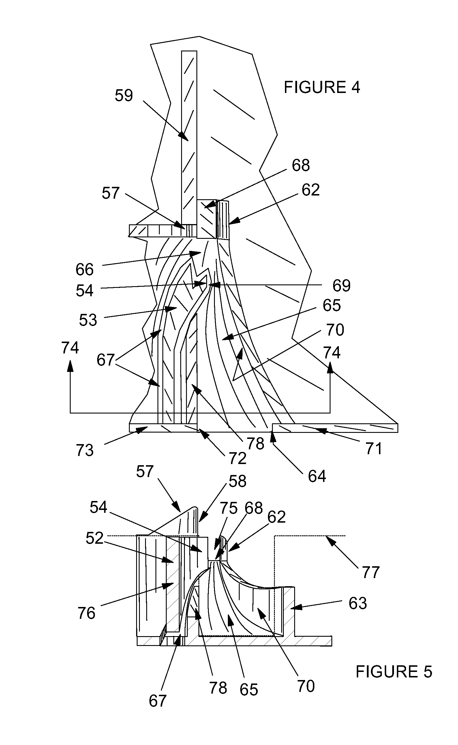
[0067]Blade remover 50 comprises a first blade guide is an opening defined by a bottom of upward ramp 65 and sidewall edges 64 and 72. It is through this opening that the forwardmost part of the bladed end of the scalpel is inserted in a first operating step of the blade remover. A particularly critical aspect of the invention is upward ramp 65. Ramp 65 extends upward from about a 15 to 75 degree angle rela...


PUM

PropertyMeasurementUnit
Lengthaaaaaaaaaa
Angleaaaaaaaaaa
Angleaaaaaaaaaa

Abstract

The present invention includes a scalpel blade removal device with an opening in a wall defining a first blade guide, extending to a narrowing upward ramp bounded by left and right guide walls. A horizontal top ramp extends from the distal end of the upward ramp, bounded by left and right guide towers. A spring loaded notch device is adapted to lock behind a proximal end of a scalpel blade seated on a scalpel, where the scalpel is inserted in the opening and the blade edge is driven up the ramp to the top ramp. When the notch device is locked behind that end of the scalpel blade, the scalpel is pulled back, causing the scalpel blade to slide off the scalpel handle. A sharps container incorporates the removal device, a reinforced latch, a scalpel resting location, and needle cover removers.

Description

[0001]This application claims the benefit of a provisional application with Ser. No. 61 / 454,477 filed Mar. 18, 2011, which application is hereby incorporated herein by reference and from which priority is hereby claimed under 35 U.S.C. Sections 119(e) and 120. Further, this application is a continuation in part of the utility patent application Ser. No. 10 / 706,353, filed Nov. 12, 2003 (Title: Scalpel Blade Remover and Sharps Container; Inventors: Mike Hoftman, William Baer), now issued as U.S. Pat. No. 8,596,453 on Dec. 3, 2013.BACKGROUND OF THE INVENTION[0002]The present invention relates to the removal of blades from scalpel handles.[0003]During or at the end of a surgical procedure, disposable scalpel blade must be removed from non-disposable scalpel handles. During surgery, some of the disposable blades may get dull or become contaminated and must be replaced by new sharp, sterile blades.[0004]A prior art scalpel handle 10 is shown in FIG. 1 and has a handle portion 12 and a nar...

Claims


Application Information

Patent Timeline
IPC IPC(8): B23P19/02B65D85/00
CPCA61B17/3217Y10T29/53683Y10T29/53943
Inventor HOFTMAN, MOSHE, MIKE
Owner HOFTMAN MOSHE MIKE
Why Eureka
Try Eureka