Supercharge Your Innovation With Domain-Expert AI Agents!

Projector

a projector and projector technology, applied in the field of projectors, can solve the problems of deteriorating image quality, falling or shifting of projection lenses, and breaking of optical components, and achieve the effect of stable condition

Active Publication Date: 2014-06-17
SEIKO EPSON CORP
View PDF9 Cites 8 Cited by
  • Summary
  • Abstract
  • Description
  • Claims
  • Application Information

AI Technical Summary

Benefits of technology

This design maintains the projection lens in a stable position, ensuring high-quality image projection by preventing shifts and falls, even with heavy short-focus lenses, and simplifies manufacturing by accurate component placement and reduced distortion loads.

Problems solved by technology

According to the technology disclosed in JP-A-2010-211114, however, the projection lens may fall down or shift with respect to the optical component housing, or the optical component housing may break, which conditions occur in some cases by the weight of the projection lens, or shock or the like applied to the projector.
When the fall or shift of the projection lens or the breakage of the optical component housing is caused, the optical axis of the projection lens shifts from the optical axis of the optical systems contained in the optical component housing, in which condition the quality of the projected image deteriorates.
When the projection lens is provided with the short-focus lens capable of performing proximity projection, this problem becomes more serious due to the heavier weight of the projection lens.

Method used


Image

  • Projector
  • Projector
  • Projector

Examples


modified examples

[0131]This embodiment can be modified in the following manners.

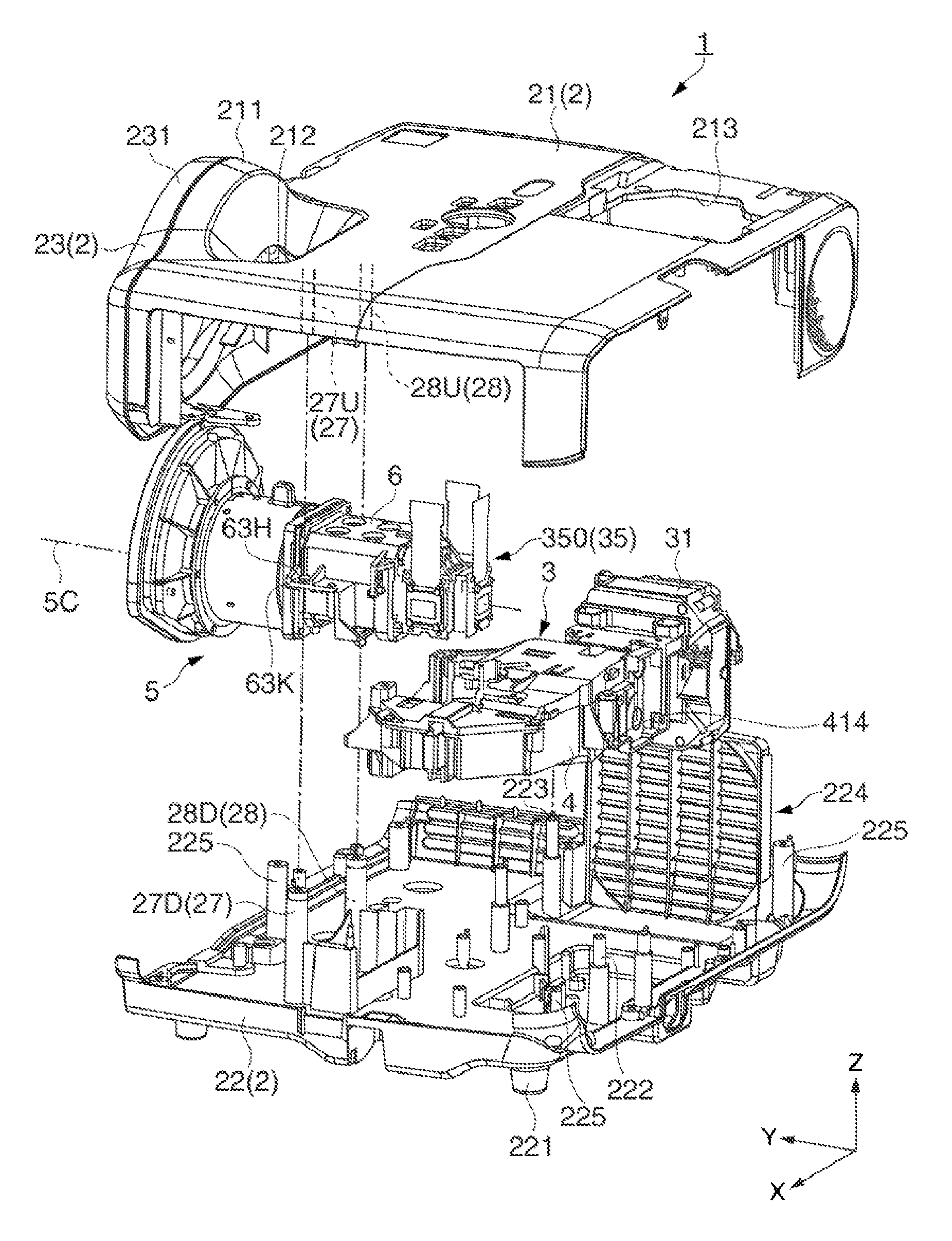
[0132]According to this embodiment, the clamping portions hold the holding unit 6. However, the clamping portions may hold the projection lens 5 instead of the holding unit 6. For example, the clamping portions may hold a clamped portion provided on the flange 521 as a part to be clamped by the clamping portions.

[0133]According to this embodiment, the first clamping portion 27 and the second clamping portion 28 are equipped as parts on the external housing 2. However, the first and second clamping portions 27 and 28 may be provided separately from the external housing 2.

[0134]Additional members (such as insulator and height adjustment spacer) may be provided between the upper clamping portions 27U and 28U and the clamped portions 63K and 64K, or between the lower clamping portions 27D and 28D and the clamped portions 63K and 64K.

[0135]While the projector 1 in this embodiment performs zoom control by using an electronic z...


PUM


Abstract

A projector includes: alight source; a light modulation device configured to modulate light emitted from the light source according to image information; a projection lens configured to project the light modulated by the light modulation device; a holding unit that holds the projection lens; an external housing that accommodates the projection lens and the holding unit; and a clamping portion that projects from the inner surface of the external housing and clamps the projection lens or the holding unit in a direction substantially perpendicular to the optical axis of the projection lens.

Description

BACKGROUND[0001]1. Technical Field[0002]The present invention relates to a projector.[0003]2. Related Art[0004]There is a projector known in the art which includes a light modulation device modulating light emitted from a light source according to image information, and a projection lens projecting the light modulated by the light modulation device, as an apparatus capable of projecting an image on a screen or other projection surfaces (for example, see JP-A-2010-211114). In recent years, such a projector has been also proposed which has a short-focus lens capable of projecting an image from a position near the projection surface (proximity projection).[0005]The projector disclosed in JP-A-2010-211114 includes an optical component housing, and a holding unit attached to the optical component housing. The optical component housing accommodates optical systems in the range from the light source up to the light modulation device. The holding unit holds the projection lens (projection d...

Claims


Application Information

Patent Timeline
Patent Type & Authority Patents(United States)
IPC IPC(8): G03B21/14
CPCG03B21/142G03B21/14G03B21/145
Inventor SAITO, MASAHIROSAKAGAMI, KEISUKEHORIKO, YUKIHIRO
Owner SEIKO EPSON CORP
Features
  • R&D
  • Intellectual Property
  • Life Sciences
  • Materials
  • Tech Scout
  • Unparalleled Data Quality
  • Higher Quality Content
  • 60% Fewer Hallucinations
Learn More