Electro-optic displays with touch sensors and/or tactile feedback

a technology of optical displays and touch sensors, applied in the field of optical displays, can solve the problems of not being able to use any display structure for touch sensing, and achieve the effect of tighter integration of touch screens

Active Publication Date: 2014-06-17
E INK CORPORATION
View PDF146 Cites 86 Cited by
  • Summary
  • Abstract
  • Description
  • Claims
  • Application Information

AI Technical Summary

Benefits of technology

[0039]In one aspect, this invention provides several methods for integrating capacitive touch sensors into a front plane laminate to produce a single film ready for assembly into a display. Electrophoretic and other bistable electro-optic media allow tighter integration of touch screens than is possible in liquid crystal displays because the bistable nature of the electro-optic medium potentially allows multiplexing of various electrode structures within the display between driving the display and sensing user input. This is not possible in liquid crystal displays; since such displays need to be driven continuously, no opportunity exists for using any display structures for touch sensing.

Problems solved by technology

This is not possible in liquid crystal displays; since such displays need to be driven continuously, no opportunity exists for using any display structures for touch sensing.

Method used


Image

  • Electro-optic displays with touch sensors and/or tactile feedback
  • Electro-optic displays with touch sensors and/or tactile feedback
  • Electro-optic displays with touch sensors and/or tactile feedback

Examples


Embodiment Construction

[0091]As indicated above, in one aspect the present invention provides several methods for integrating capacitive touch sensors into a front plane laminate to produce a single film ready for assembly into a display.

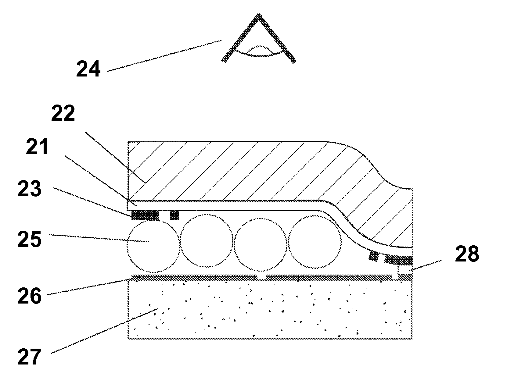
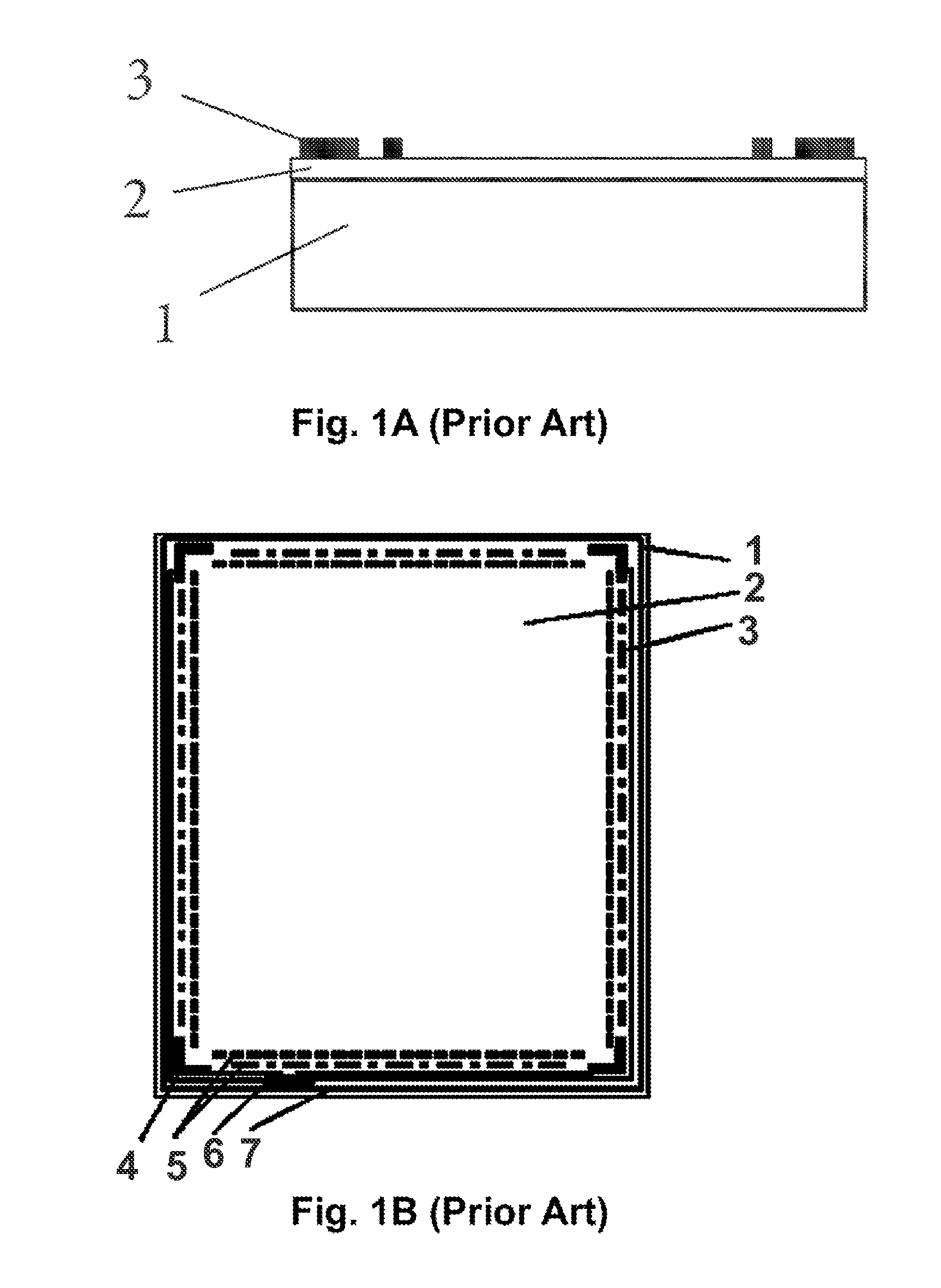
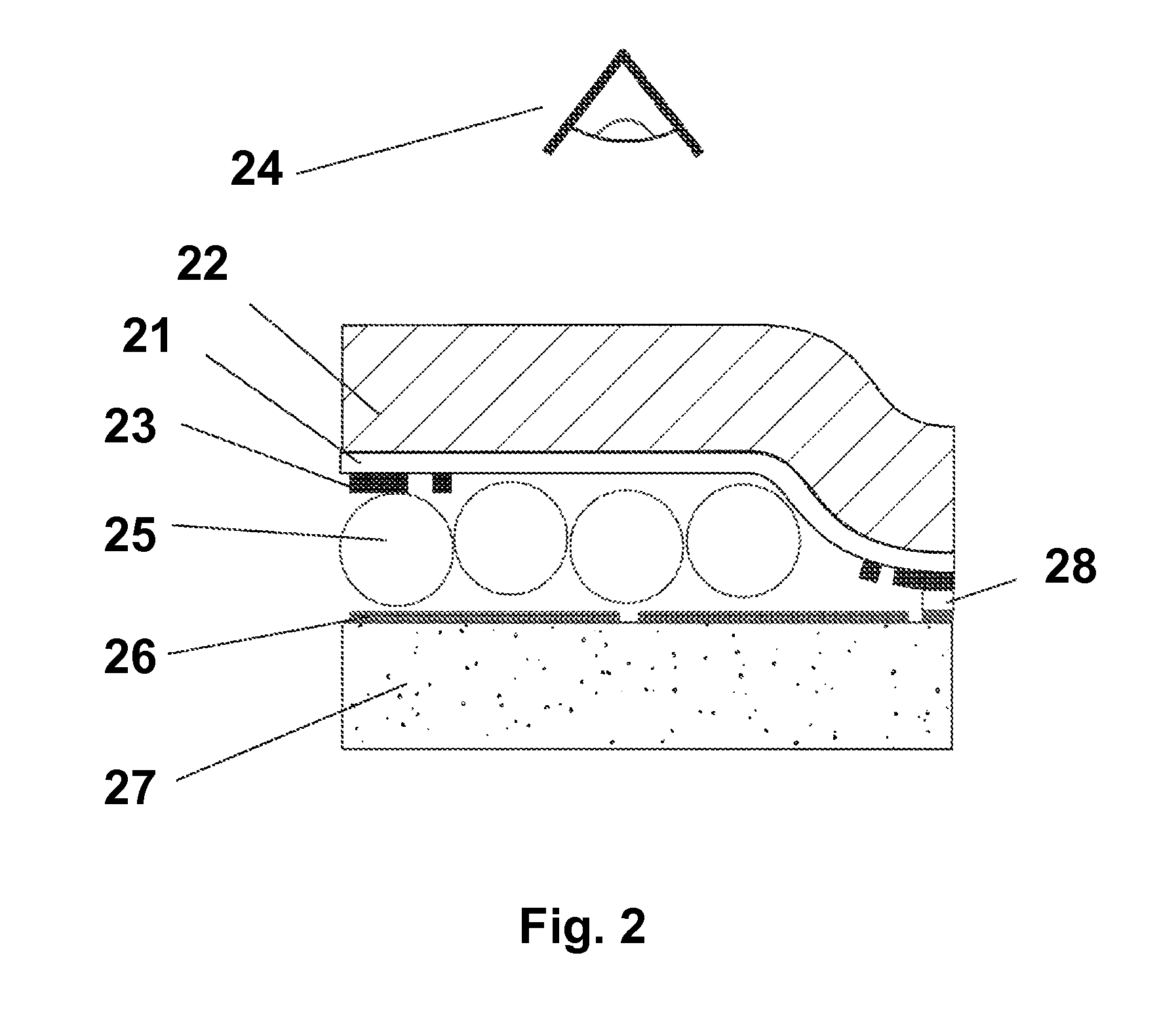
[0092]As illustrated in FIG. 2, the most straightforward way to effect such integration is to make a single conductive layer 21 serve as both the conductive layer of the touch screen and the top electrode of the display. In the structure of FIG. 2, a front substrate 22, which serves as both the substrate of the touch screen and the front substrate of the display, faces a viewer 24. The low sheet resistance material 23 (similar to the material 3 in FIGS. 1A and 1B) lies adjacent an electro-optic layer (illustrated as a microencapsulated electrophoretic layer 25) provided with pixel electrodes 26 on a backplane 27. (Although not shown in FIG. 2, there is normally a layer of lamination adhesive between the electro-optic layer 25 and the pixel electrodes 26; there may also be...


PUM

PropertyMeasurementUnit
diameteraaaaaaaaaa
thicknessaaaaaaaaaa
thicknessaaaaaaaaaa

Abstract

An electro-optic display comprises, in order, a light-transmissive electrically-conductive layer; a layer of a solid electro-optic material; and a backplane (162) bearing a plurality of pixel electrodes. A peripheral portion of the backplane extends outwardly beyond the layer of solid electro-optic material and bears a plurality of radiation generators (166) and a plurality of radiation detectors (168), the radiation generators and detectors together being arranged to act as a touch screen.

Description

REFERENCE TO RELATED APPLICATIONS[0001]This application claims benefit of copending Application Ser. No. 61 / 255,580, filed Oct. 28, 2009.[0002]This application is related to:[0003](a) U.S. Pat. Nos. 6,473,072 and 6,738,050;[0004](b) U.S. Pat. Nos. 7,030,854; 7,312,784; and 7,705.824;[0005](c) U.S. Pat. No. 6,392,786;[0006](d) U.S. Pat. No. 7,110,164; and[0007](e) U.S. Pat. Nos. 6,473,072 and 6,738,050.[0008]The entire contents of these patents and application, and of all other U.S. patents and published and copending applications mentioned below, are herein incorporated by reference.BACKGROUND OF INVENTION[0009]This application relates to electro-optic displays provided with touch sensors and / or tactile feedback. This invention is primarily directed to such electro-optic displays which use solid electro-optic media, as that term is defined below.[0010]The term “electro-optic”, as applied to a material, medium or a display, is used herein in its conventional meaning in the imaging ar...

Claims


Application Information

Patent Timeline
Patent Type & Authority Patents(United States)
IPC IPC(8): G06F3/041G02B6/06G02F1/03G02F1/167G02F1/16757G02F1/1676
CPCG06F3/044G02F1/13338G02F1/167G06F3/0421G06F3/0414G06F3/0412G06F3/04886G06F3/045G02F1/0018G02F1/1676G02F1/16757G06F3/04164G06F3/04166G06F3/0443G06F3/042G09G3/344G09G2300/04G02B23/2407G09G2354/00G02F1/1681
Inventor GATES, HOLLY G.ZEHNER, ROBERT W.WILCOX, RUSSELL J.APREA, MATTHEW J.
Owner E INK CORPORATION
Why Eureka
Try Eureka