Electrophoretic display device and electronic apparatus

a display device and display face technology, applied in the field of electrotrophoretic display devices and electronic devices, can solve the problems of variation, deterioration of the design property of the display device, and adverse effects on the appearance of the display face, and achieve excellent design properties and excellent display characteristics

Active Publication Date: 2014-06-17
E INK CORPORATION
View PDF5 Cites 0 Cited by
  • Summary
  • Abstract
  • Description
  • Claims
  • Application Information

AI Technical Summary

Benefits of technology

[0006]An advantage of some aspects of the invention is that it provides an electrophoretic display device and an electronic apparatus, in which even in a case where position misalignment has occurred at the time of bonding of substrates, deterioration of the design property and the appearance is prevented.

Problems solved by technology

However, in the related art described above, since the display face is at a deep position with respect to a surface at which printing is carried out on the cover member due to the display layer, there is a problem in that the boundary between the printed surface and the display face is noticeable, whereby the design property of the display device is deteriorated and the appearance of the display face is also adversely affected.
Also, there is a fear that a variation occurs in bonding position precision at the cover member and there is also a fear that a variation occurs in the printed position itself of the sacrifice layer or the like.
Then, a display area is deviated from a design position, such that, especially in a case where the EPD display device is used in a small-size application, the appearance is significantly deteriorated even if there is minute position misalignment of the display area.

Method used


Image

  • Electrophoretic display device and electronic apparatus
  • Electrophoretic display device and electronic apparatus
  • Electrophoretic display device and electronic apparatus

Examples


first embodiment

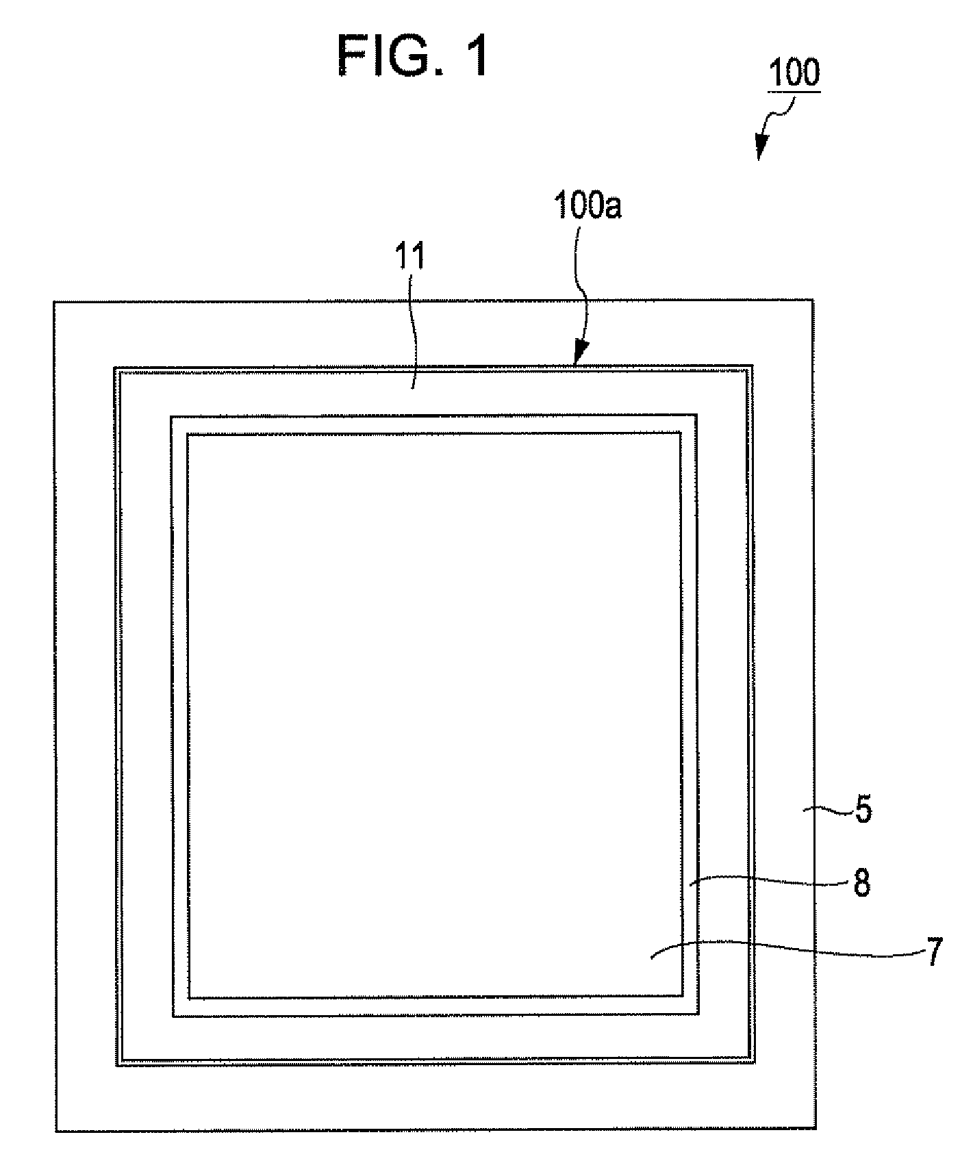
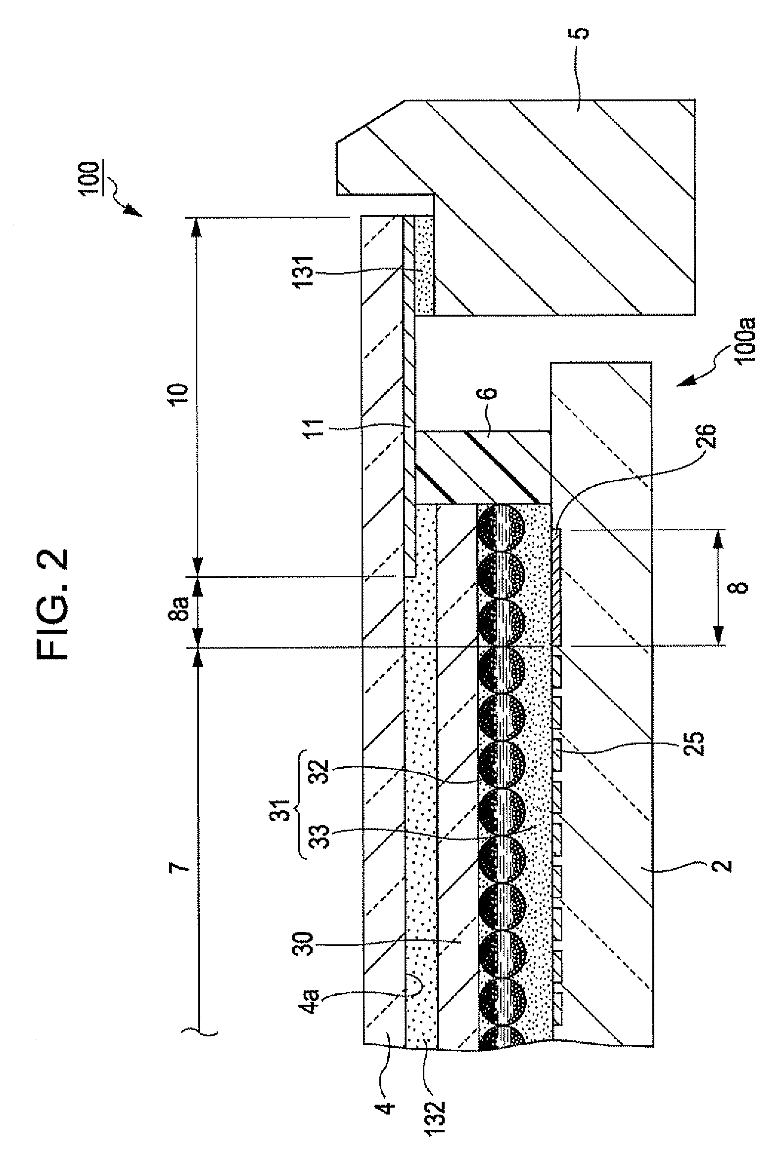
[0031]FIG. 1 is a plan view showing a configuration related to one embodiment of an electrophoretic display device and FIG. 2 is a diagram showing a cross-sectional configuration related to a main section of the electrophoretic display device.

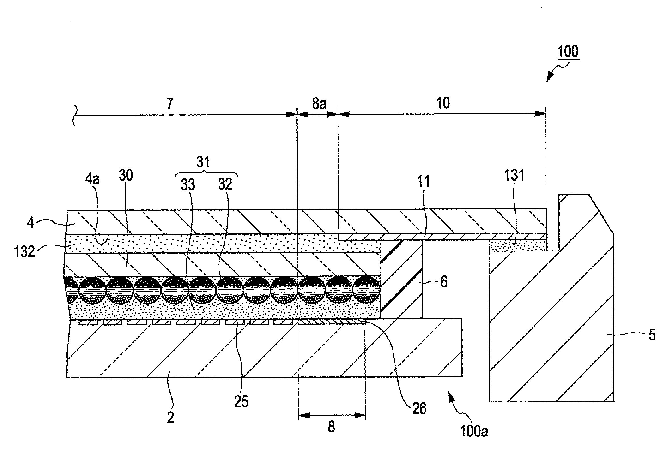
[0032]As shown in FIG. 1, an electrophoretic display device 100 includes a panel section 100a and a casing section 5 which holds the panel section 100a. The panel section 100a includes an element substrate (a first substrate) 2, a transparent substrate 30, an electrophoretic layer 31 which is sandwiched in between these substrates 2 and 30, a glass substrate (a second substrate) 4, and a sealing member 6, as shown in FIG. 2.

[0033]The glass substrate 4 is bonded to the transparent substrate 30 through an adhesive layer 132. The sealing member 6 is disposed between the glass substrate 4 and the element substrate 2 so as to surround the electrophoretic layer 31. The glass substrate 4 is formed in a state where the planar shape thereof extends furt...

second embodiment

[0055]Next, a configuration related to the second embodiment of the electrophoretic display device will be described. A difference between the configurations related to this embodiment and the first embodiment is to adopt the same pixel structure as the display area 7 for the sacrifice display area. Here, the same pixel structure means that as shown in FIG. 4, a plurality of electrodes for sacrifice display 26 each having approximately the same size as the pixel electrode 25 is disposed approximately in a matrix form at the sacrifice display area 8 and a region where each electrode for sacrifice display 26 is formed becomes a pixel region and has a pixel structure 26a capable of displaying various images for each pixel region. A driving layer (not shown) which includes a switching element is provided at each of the electrodes for sacrifice display 26 and the electrode for sacrifice display 26 can be driven independently of the pixel electrode 25. In addition, in other respects, the ...


PUM

PropertyMeasurementUnit
thicknessaaaaaaaaaa
thicknessaaaaaaaaaa
thicknessaaaaaaaaaa

Abstract

An electrophoretic display device includes: an electrophoretic layer which is sandwiched between a first substrate and a second substrate, wherein a disposition area of the electrophoretic layer is constituted by a display area and a sacrifice display area which is provided to surround the display area, and at the second substrate, a printed area which is set outside the display area in a plan view and overlaps an outer peripheral portion of the sacrifice display area is provided.

Description

CROSS-REFERENCE TO RELATED APPLICATION[0001]This application is based on and claims priority from Japanese Patent Application No. 2010-098856, filed on Apr. 22, 2010, the contents of which are incorporated herein by reference.BACKGROUND[0002]The present invention relates to an electrophoretic display device and an electronic apparatus.RELATED ART[0003]At present, display devices such as liquid crystal devices are used in each field of mobile telephones, televisions, clocks, or the like and are being developed more and more, and development is rapidly proceeding of devices which have narrower frames, are slimmer, and are lighter weight in line with design or function needs of users. Further, along with the slimming of flat display devices, the need for a device capable of being bent or folded back, such as a flexible display device, is also growing. As the flexible display device, an electrophoretic display (EPD) capable of being made thinner and lighter, thereby having properties cl...

Claims


Application Information

Patent Timeline
Patent Type & Authority Patents(United States)
IPC IPC(8): G02B26/00G02F1/167G02F1/16757G02F1/1676
CPCG02F2001/1676G02F1/167G09G2310/0232G09G3/344G02F1/1676G02F1/16757
Inventor TERASHIMA, YASUHIROITO, WATARU
Owner E INK CORPORATION
Why Eureka
Try Eureka