

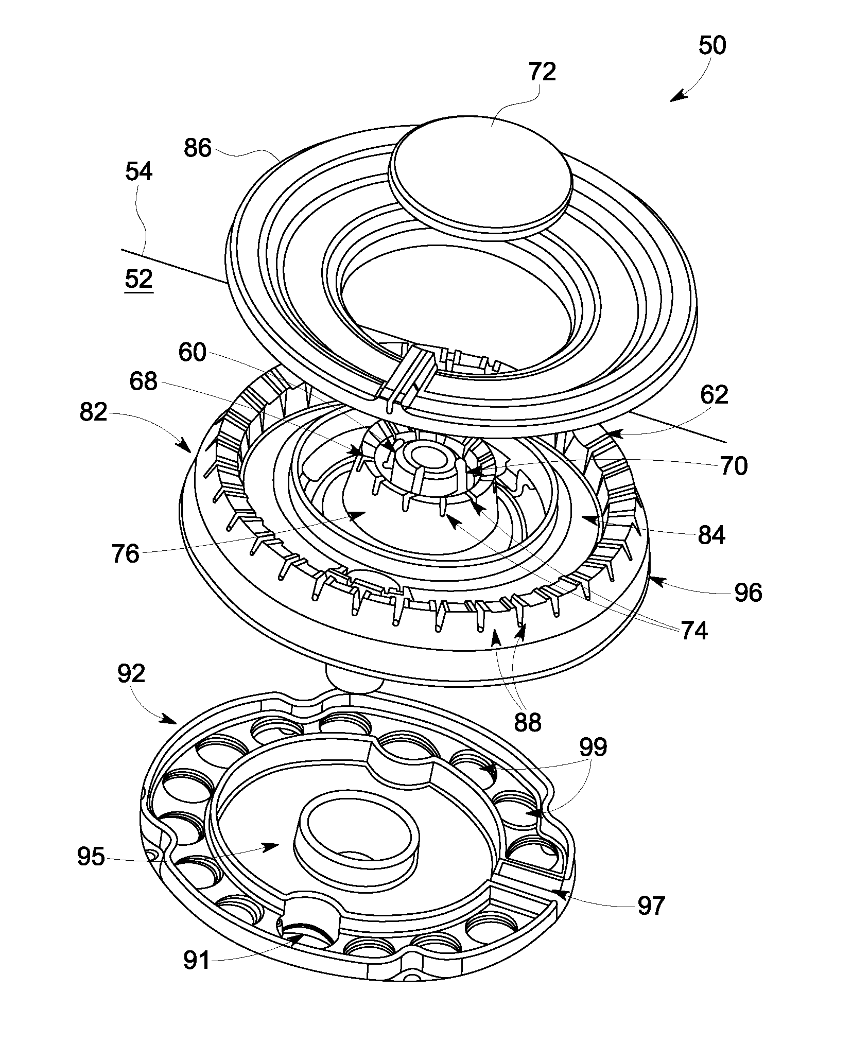
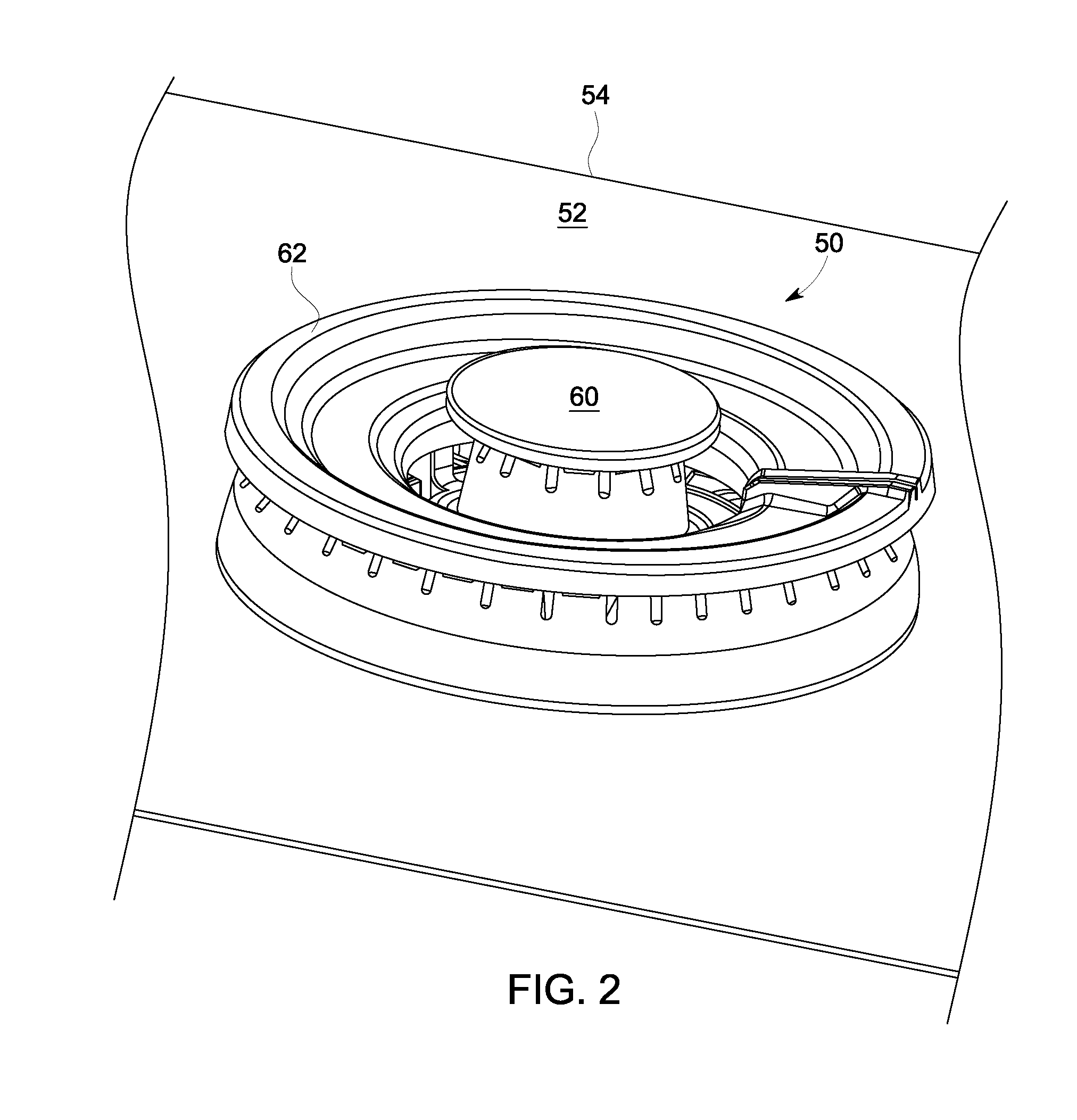
Multi-ringed burner with spill containment
a burner and multi-ring technology, applied in the field of gas appliances, can solve problems such as spills channeling around the openings
- Summary
- Abstract
- Description
- Claims
- Application Information
AI Technical Summary
Benefits of technology
Problems solved by technology
Method used
Image

Examples
Embodiment Construction
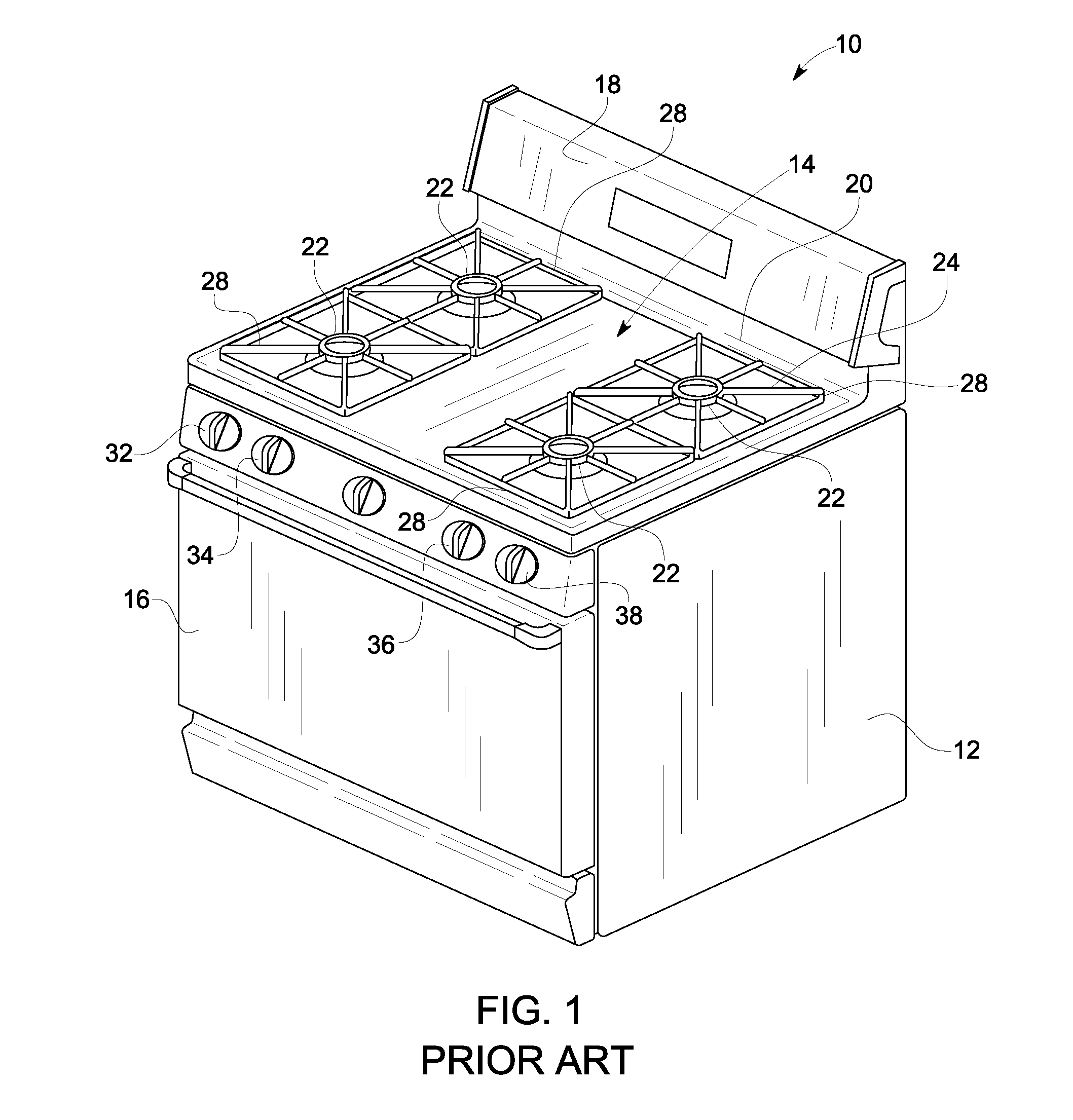
[0018]One or more illustrative embodiments of the invention will be described below in the context of an oven appliance. However, it is to be understood that embodiments of the invention are not intended to be limited to use with any particular gas appliance. Rather, embodiments of the invention may be applied to and deployed in any other suitable environment in which it would be desirable to operate a multi-ring burner.
[0019]As illustratively used herein, the term “appliance” is intended to refer to a device or equipment designed to perform one or more specific functions. This may include, but is not limited to, equipment for consumer use, e.g., a gas range on a freestanding oven. This may include, but is not limited to, any equipment that is useable in household or commercial environments.
[0020]While the methods and apparatus are herein described in the context of a gas-fired cooktop, as set forth more fully below, it is contemplated that the herein described methods and apparatus...
PUM
 Abstract
Description
Claims
Application Information