
Electric socket and bearing body therefor

a technology of bearing body and electric socket, which is applied in the direction of coupling device connection, coupling parts engagement/disengagement, incorrect coupling prevention, etc., can solve the problems of connecting terminals not being stably and firmly combined with electric sockets, damage to them, and affecting the operation of connecting terminals. , to achieve the effect of preventing damage to electronic devices and peripherals

Active Publication Date: 2014-06-24
GIGA BYTE TECH CO LTD
View PDF14 Cites 3 Cited by
  • Summary
  • Abstract
  • Description
  • Claims
  • Application Information

AI Technical Summary

Benefits of technology

[0008]In view of the forgoing problem, the invention discloses an electric socket and a bearing body for the electric socket, both of which are capable of keeping the connecting terminals from loose connection, slip, or detachment. They solve the conventional problem by preventing the damage to the electronic devices and peripherals.
[0011]The object of the invention can be achieved by providing an electric socket and a bearing body therefor that are capable of binding the connecting terminal to the electric socket firmly by way of the baffled portion and the rib. Among them, because the rib helps with increase of the contact area between the electric socket and the connecting terminal, the friction therebetween is also increased. This further prevents the detachment of the connecting terminal from the electric socket.

Problems solved by technology

For this reason, the force acting upon the connecting terminals tends to be not uniform, thus the connecting terminals cannot combine stably and firmly with the electric sockets.
Under this condition, unstable transmission between the electronic devices and the peripherals may occur, thereby causing the damage thereto.

Method used


Image

  • Electric socket and bearing body therefor
  • Electric socket and bearing body therefor
  • Electric socket and bearing body therefor

Examples


Embodiment Construction

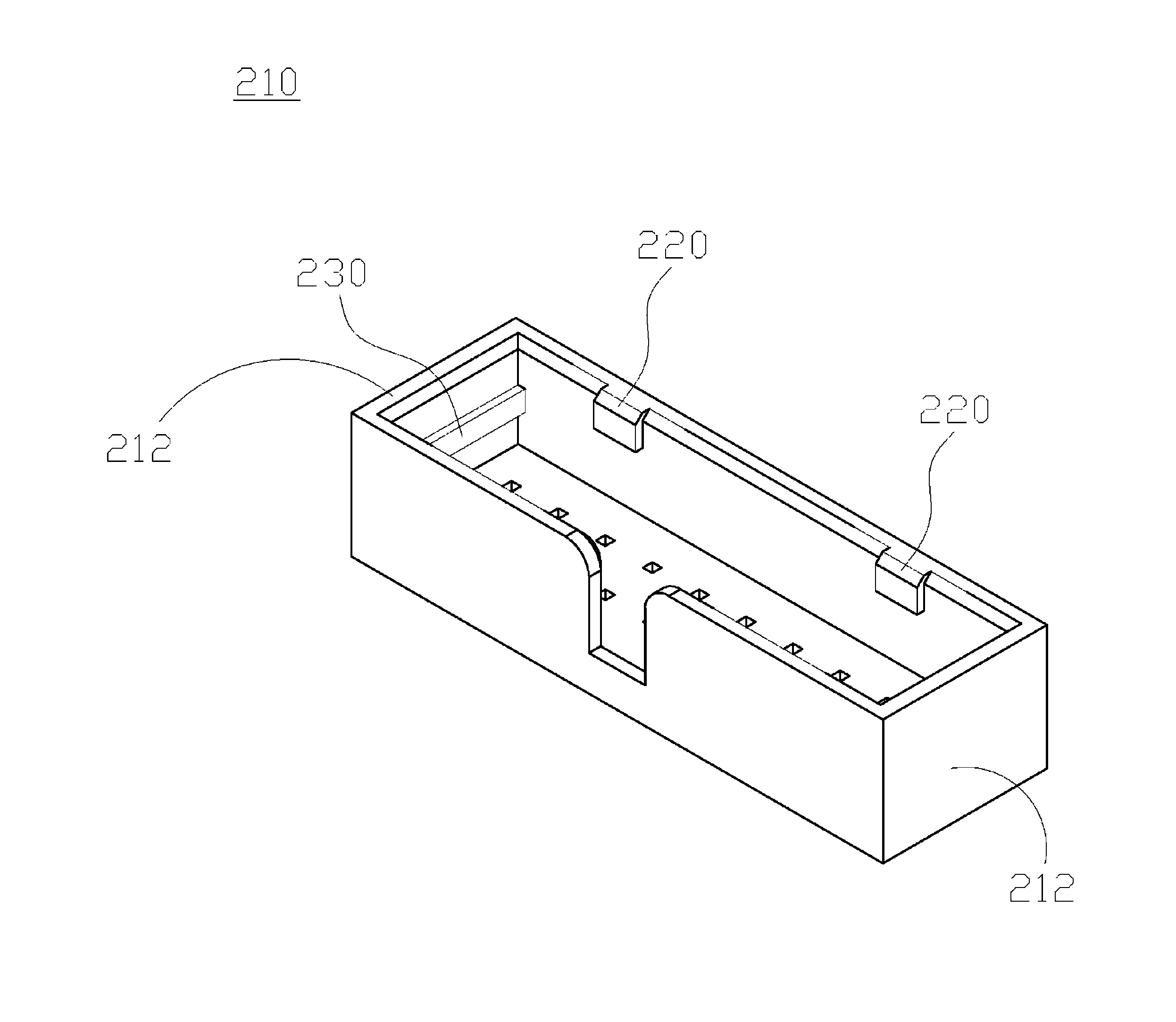
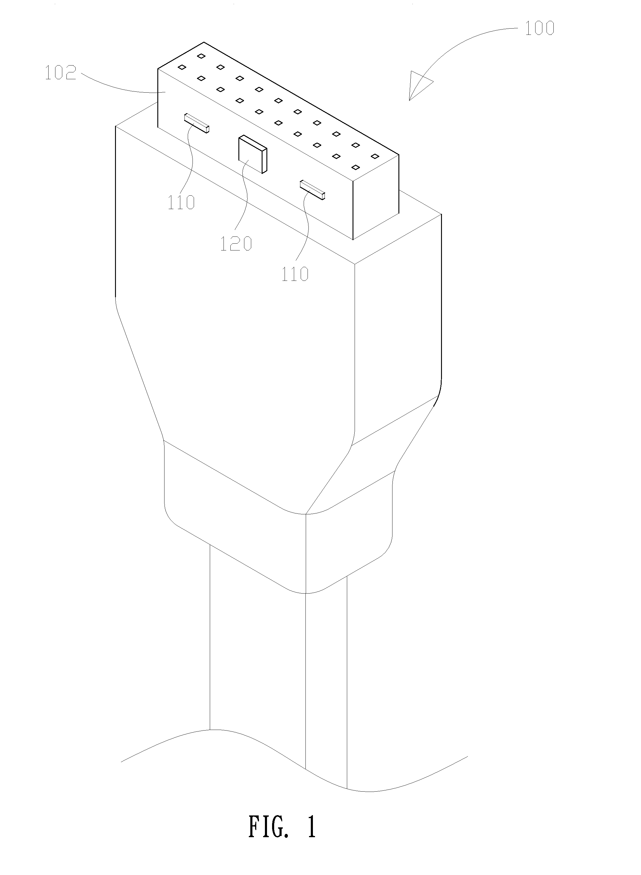
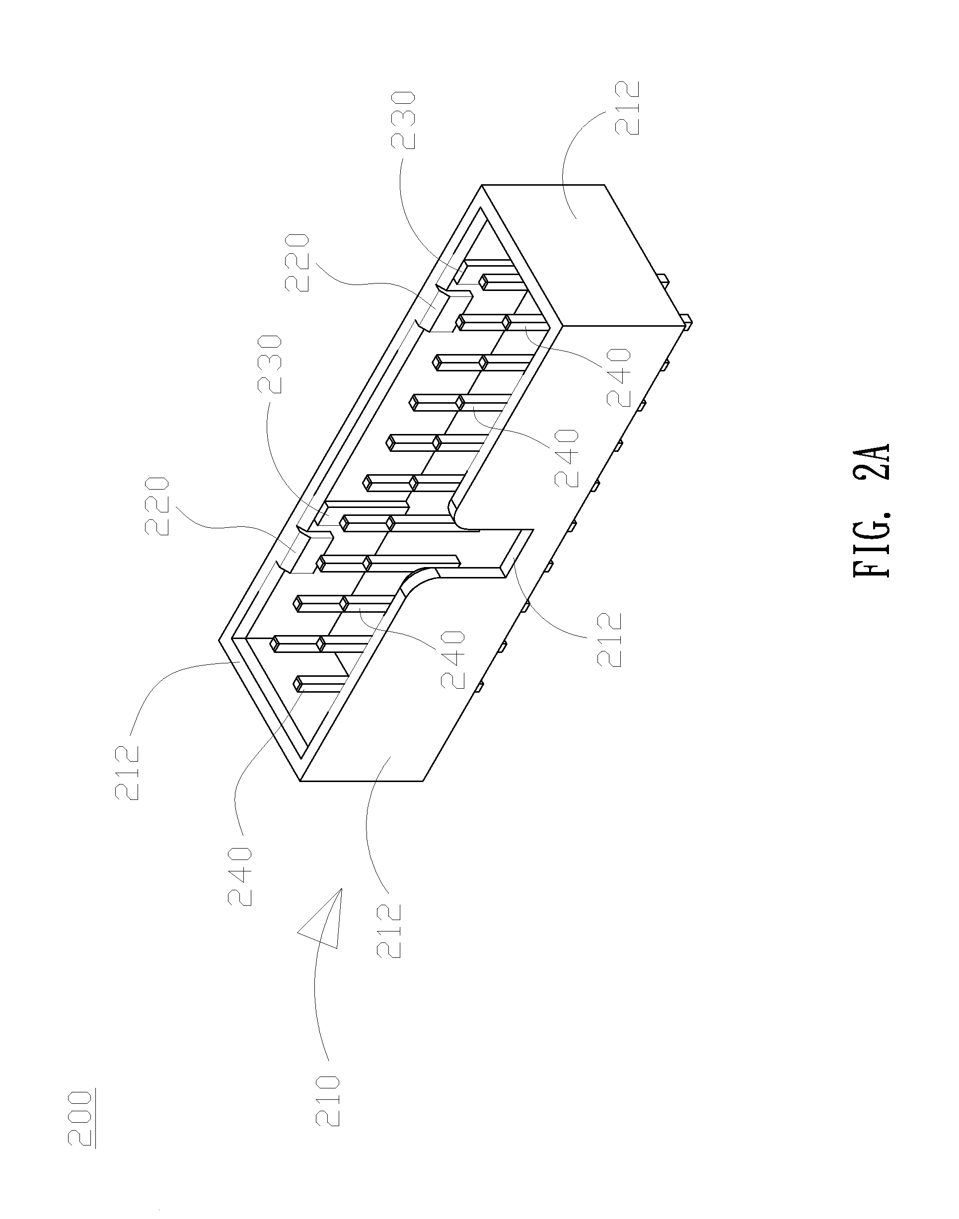
[0033]FIGS. 1 and 2A-2C are respectively a schematic view showing the structure of the electrically connecting terminal, a three-dimensional view and an exploded view of the electric socket, and a bearing body of the electric socket of a first preferred embodiment of the invention.

[0034]As shown in the figures, the electric socket 200 of the invention is fit for an electrically connecting terminal 100 having a fastener 110 and a guide bump 120 on an outer surface 102 thereof. The electric socket 200 includes a housing 210, a baffled portion 220, a rib 230, and a plurality of conductive pins 240. The housing 210 is surrounded by multiple sidewalls 212 and a housing 214 is formed therein for accommodating connecting terminals 100. The baffled portion 220 is provided on a sidewall at a position corresponding to the fastener 110. In this embodiment, two baffled portions 220 are formed in an electric socket for illustration.

[0035]The rib 230 is provided on the same sidewall that the baff...


PUM


Abstract

The invention provides an electric socket and a bearing body therefor. The bearing body includes a housing for accommodating the electrically connecting terminal, having a plurality of sidewalls that are connected and a bottom; a baffled portion on one of the sidewalls; a rib provided on the sidewall and extending longitudinally from one side to the other side of the one of the sidewalls; and a plurality of conductive pins penetrating the bottom. When the electrically connecting terminal is fit into the housing, the baffled portion opposes against the fastener of the electrically connecting terminal, and the rib is located against an outer surface of the electrically connecting terminal, thereby preventing detachment of the electrically connecting terminal from the electric socket.

Description

CROSS-REFERENCE OF RELATED APPLICATIONS[0001]This application claims the benefit of the priority of Taiwan Patent Application No. TW 100120795, entitled “ELECTRIC SOCKET AND BEARING BODY THEREFOR”, filed on Jun. 15, 2011, the entirety of which is incorporated herein by reference.BACKGROUND OF THE INVENTION[0002]1. Field of the Invention[0003]The invention relates to an electric socket and a bearing body for the electric socket, particularly relates to an electric socket capable of preventing slip, loose connection, or detachment of an electrically connecting terminal therefrom and a bearing for the electric socket.[0004]2. Description of the Prior Art[0005]As the technology greatly advances, the trend for most high-tech products is moving towards powerful function, miniaturization, and easy extendibility. In order to connect with modern peripherals, there are many different types of electric connectors on circuit boards of electronic products.[0006]The electric connector that is wid...

Claims


Application Information

Patent Timeline
Patent Type & Authority Patents(United States)
IPC IPC(8): H01R13/627H01R13/62
CPCH01R13/62
Inventor CHANG, YA-HANKAO, YUNG-SHUN
Owner GIGA BYTE TECH CO LTD
Learn More