
Power supply circuit

a power supply circuit and power supply technology, applied in the direction of power conversion systems, dc-dc conversion, dc source parallel operation, etc., can solve the problems of comparatively high photocoupler cost and the inability to directly feed back the positive-side supply voltage of the second power supply to the switching controller, so as to increase the fluctuation sensitivity of the positive-side supply voltage of the second power supply

Inactive Publication Date: 2014-06-24
ONKYO KK
View PDF13 Cites 2 Cited by
  • Summary
  • Abstract
  • Description
  • Claims
  • Application Information

AI Technical Summary

Benefits of technology

[0014]In this case, fluctuation sensitivity of the positive-side supply voltage of the second power supply can be heightened.

Problems solved by technology

However, since the first power supply and the second power supply have the different reference potentials, the positive-side supply voltage of the second power supply cannot be directly fed back to the switching controller.
However, since the photocoupler is comparatively expensive, there is demanded a power supply circuit that feeds back the positive-side supply voltage of the second power supply to the switching controller without using the photocoupler.

Method used


Image

  • Power supply circuit
  • Power supply circuit
  • Power supply circuit

Examples


Embodiment Construction

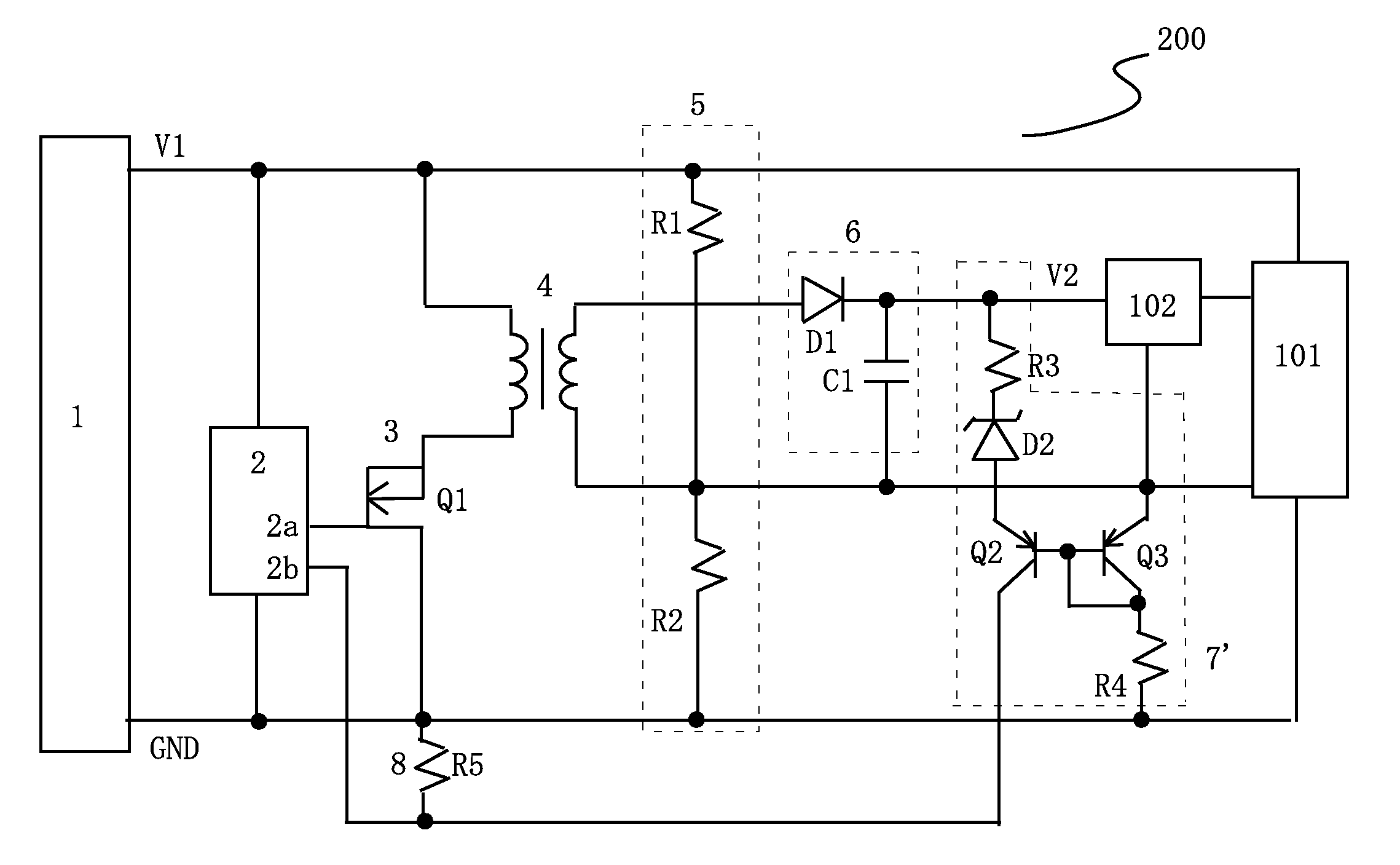
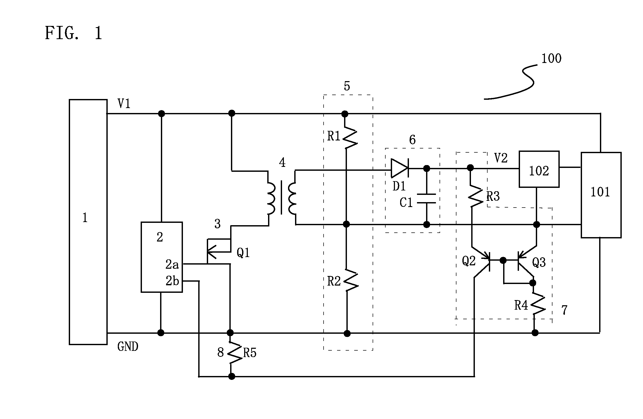
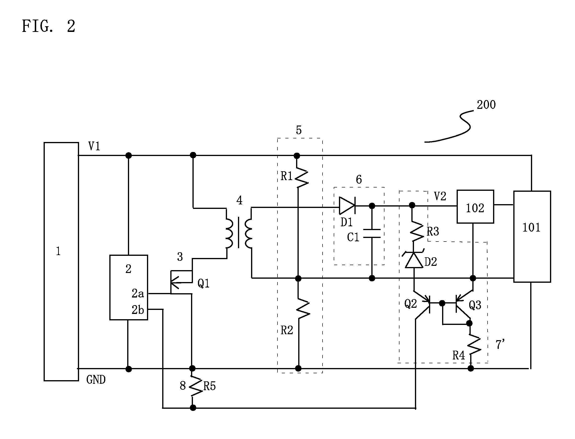
[0017]Preferred embodiments of the present invention will be specifically described below with reference to the drawings, but the present invention is not limited to the embodiments. FIG. 1 is a circuit block diagram illustrating a power supply circuit 100 according to the preferred embodiment of the present invention. The power supply circuit 100 generally has a first power supply 1, a switching controller 2, a switching element 3, a switching transformer 4, a reference potential generating section 5, a second power supply generating section 6, a current mirror circuit 7, and a current / voltage converting section 8.

[0018]The reference potential generating section 5 and the second power supply generating section 6 constitute a second power supply. The switching controller 2, the switching element 3, and the switching transformer 4 constitute a switching power supply. The current mirror circuit 7 and the current / voltage converting section 8 constitute a feedback circuit.

[0019]The firs...


PUM


Abstract

A current mirror circuit converts a positive-side supply voltage of a second power supply with respect to a reference potential into an electric current so as to supply the electric current to a current / voltage converting section. The current / voltage converting section converts the electric current from the current mirror circuit into a voltage with respect to the reference potential of a first power supply so as to supply the voltage to a feedback input terminal of a switching controller. Therefore, although the reference potential of the first power supply supplied to the switching controller is different from the reference potential of the second power supply, the electric current from the current mirror circuit is not influenced by the reference potential.

Description

BACKGROUND OF THE INVENTION[0001]1. Field of the Invention[0002]The present invention relates to a power supply circuit having a first power supply as a single power supply and a second power supply as a single power supply.[0003]2. Description of the Related Art[0004]Some audio devices have a circuit operated by a first power supply as a single power supply and a circuit operated by a second power supply as a single power supply whose voltage is different from that of the first power supply. The single power supply includes a positive-side supply voltage and a reference potential such as a ground potential. The second power supply includes the positive-side supply voltage that is generated by switching and operating the positive-side supply voltage of the first power supply by means of a switching element, and a reference potential that is generated by dividing the positive-side supply voltage of the first power supply. A switching controller and the switching element are operated ...

Claims


Application Information

Patent Timeline
Patent Type & Authority Patents(United States)
IPC IPC(8): H02M3/335
CPCY10T307/50H02M3/33507
Inventor INOUE, MASAAKI
Owner ONKYO KK
Learn More