
Method and apparatus for generating three-dimensional pose using monocular visual sensor and inertial measurement unit

a monocular visual sensor and inertial measurement technology, applied in image analysis, instruments, computing, etc., can solve problems such as scale ambiguity, measurement uncertainty is severely underestimated, and outlier feature rejection becomes problemati

Active Publication Date: 2014-06-24
SRI INTERNATIONAL
View PDF4 Cites 85 Cited by
  • Summary
  • Abstract
  • Description
  • Claims
  • Application Information

AI Technical Summary

Benefits of technology

The present invention is an apparatus and method for estimating the position and orientation of an object in a three-dimensional space using a monocular camera and an inertial measurement unit (IMU). The apparatus includes a feature tracking module for identifying features in the images and an error-state filter that combines the information from the camera, IMU, and feature tracking to correct the IMU data and produce a more accurate pose estimation. The technical effect of this invention is to provide a reliable and accurate means for determining the position and orientation of an object in a three-dimensional space.

Problems solved by technology

This traditional method led to scale ambiguity problems, as actual scale could not be determined properly from the features as well as problems with uncertainty propagation due to the highly non-linear nature of pose estimation from monocular feature correspondences over several frames.
However, in such a framework, measurement uncertainty is severely underestimated due to non-linearities.
Outlier feature rejection becomes problematic, since, in order to reject bad pose measurements, one needs a mechanism to compare the predicted pose against the measurement, and the measurement suffers from a poor uncertainty model.
However, it is still unclear how to best combine the information from these complementary sensors.
However, these systems have not eliminated the problem of measurement uncertainty and scale ambiguity.

Method used


Image

  • Method and apparatus for generating three-dimensional pose using monocular visual sensor and inertial measurement unit
  • Method and apparatus for generating three-dimensional pose using monocular visual sensor and inertial measurement unit
  • Method and apparatus for generating three-dimensional pose using monocular visual sensor and inertial measurement unit

Examples


Embodiment Construction

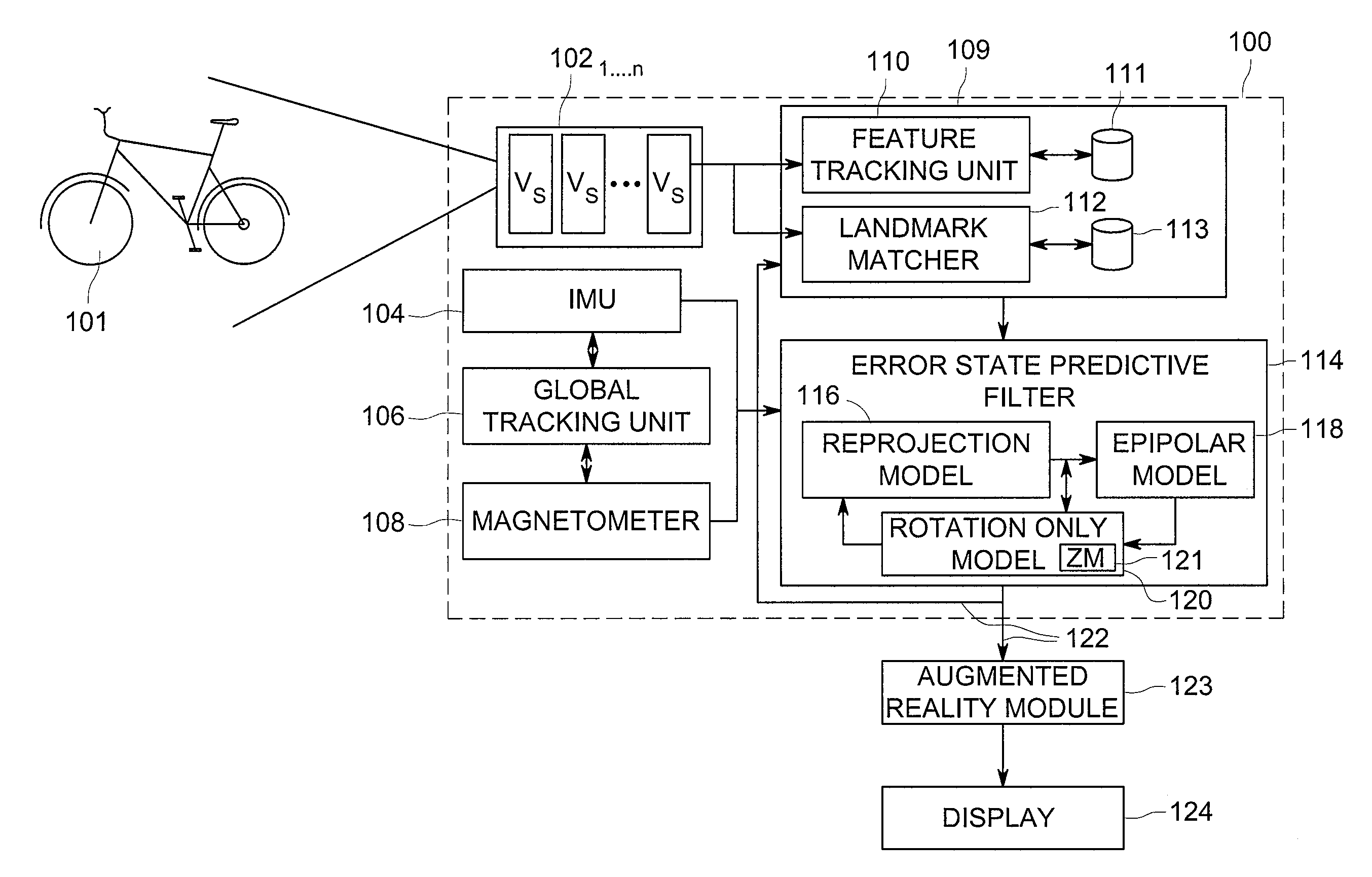
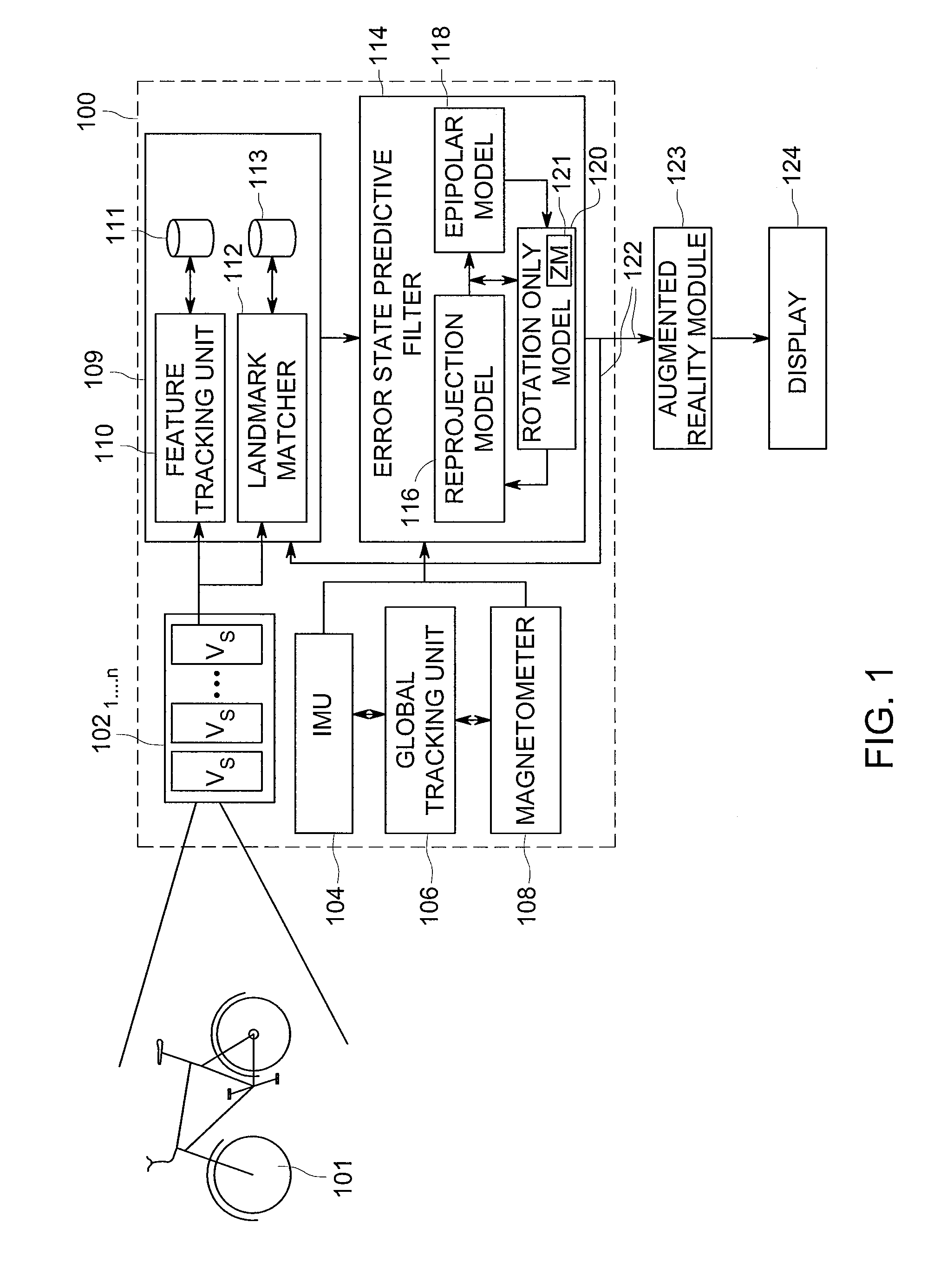
[0019]Embodiments of the present invention generally relate to generating a three-dimensional pose estimation using a monocular visual sensor and an IMU. In an exemplary embodiment, the present invention uses one or more monocular visual sensors to obtain images of a scene, tracks features in the scene to reject outliers and uses an inertial measurement unit, a global tracking unit and a magnetometer to read measurements coupled to an error-state predictive filter to generate error constraints. These error constraints coupled with the feature tracking assist the IMU, the global tracking unit and the magnetometer in calculating a more accurate final pose estimation of the visual sensor using six degrees of freedom (6dof).

[0020]FIG. 1 depicts a functional block diagram of an apparatus 100 for generating three-dimensional pose using a monocular visual sensor and an inertial measurement unit in accordance with an exemplary embodiment of the present invention. The apparatus 100 comprises...


PUM


Abstract

An apparatus for providing three-dimensional pose comprising monocular visual sensors for providing images of an environment surrounding the apparatus, an inertial measurement unit (IMU) for providing gyroscope, acceleration and velocity information, collectively IMU information, a feature tracking module for generating feature tracking information for the images, and an error-state filter, coupled to the feature track module, the IMU and the one or more visual sensors, for correcting IMU information and producing a pose estimation based on at least one error-state model chosen according to the sensed images, the IMU information and the feature tracking information.

Description

GOVERNMENT RIGHTS IN THIS INVENTION[0001]This invention was made with U.S. government support under contract number FA9200-07-D-0045 / 0016. The U.S. government has certain rights in this invention.BACKGROUND OF THE INVENTION[0002]1. Field of the Invention[0003]Embodiments of the present invention generally relate to three-dimensional navigation systems and, more particularly, to a method and apparatus for generating three-dimensional pose using a monocular visual sensor and an inertial measurement unit.[0004]2. Description of the Related Art[0005]Traditional approaches for computing pose estimations for devices using monocular visual sensors (e.g., single lens cameras) and an inertial measurement unit relied on computing a pose estimate from visually tracked features of a scene and building a measurement model, based on the pose estimate. This traditional method led to scale ambiguity problems, as actual scale could not be determined properly from the features as well as problems wit...

Claims


Application Information

Patent Timeline
Patent Type & Authority Patents(United States)
IPC IPC(8): G06K9/00
CPCG06K9/00671G06T7/004G06K9/00G06T7/0042G06T7/73
Inventor KUMAR, RAKESHSAMARASEKERA, SUPUNOSKIPER, TARAGAY
Owner SRI INTERNATIONAL
Learn More