
Combination agitating parts washer and sink washer

a technology of agitation and parts, which is applied in the direction of cleaning process and apparatus, chemistry apparatus and process, cleaning using liquids, etc., can solve the problems of environmental objection to the use of such toxic cleaning solutions, limited or severely limited the use of sink-type parts washers, etc., and achieves minimal shop floor space, low cost, and low cost

Active Publication Date: 2014-07-01
HERITAGE CRYSTAL CLEAN
View PDF35 Cites 10 Cited by
  • Summary
  • Abstract
  • Description
  • Claims
  • Application Information

AI Technical Summary

Benefits of technology

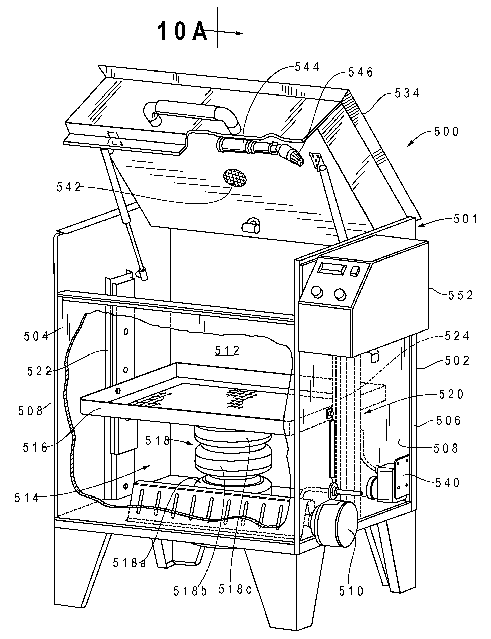
The present invention is a washer that can clean and degrease mechanical parts such as automotive parts using a water-based, biodegradable detergent solution. It can be used as a parts washing sink, a jet washer, and an agitating vat-type washer. The washer is efficient, compact, and economical to manufacture. It has a basket for receiving parts, a parts sink, and a hinged lid that can be opened to access the interior of the washer. The washer provides both automatic and manual cleaning using the water-based solution. It is portable and can be used to clean small or larger parts, making the cleaning process more efficient.

Problems solved by technology

In the past, most parts washers of the sink type utilized toxic cleaning fluids such as petroleum-based solvents and non-biodegradable detergents.
The use of such toxic cleaning solutions is environmentally objectionable and, as a result, both state and federal authorities have restricted or severely limited the uses of these types of solutions and solvents.
Sink-type parts washers, since they are manual, may be messy and time-consuming in use.

Method used


Image

  • Combination agitating parts washer and sink washer
  • Combination agitating parts washer and sink washer
  • Combination agitating parts washer and sink washer

Examples


Embodiment Construction

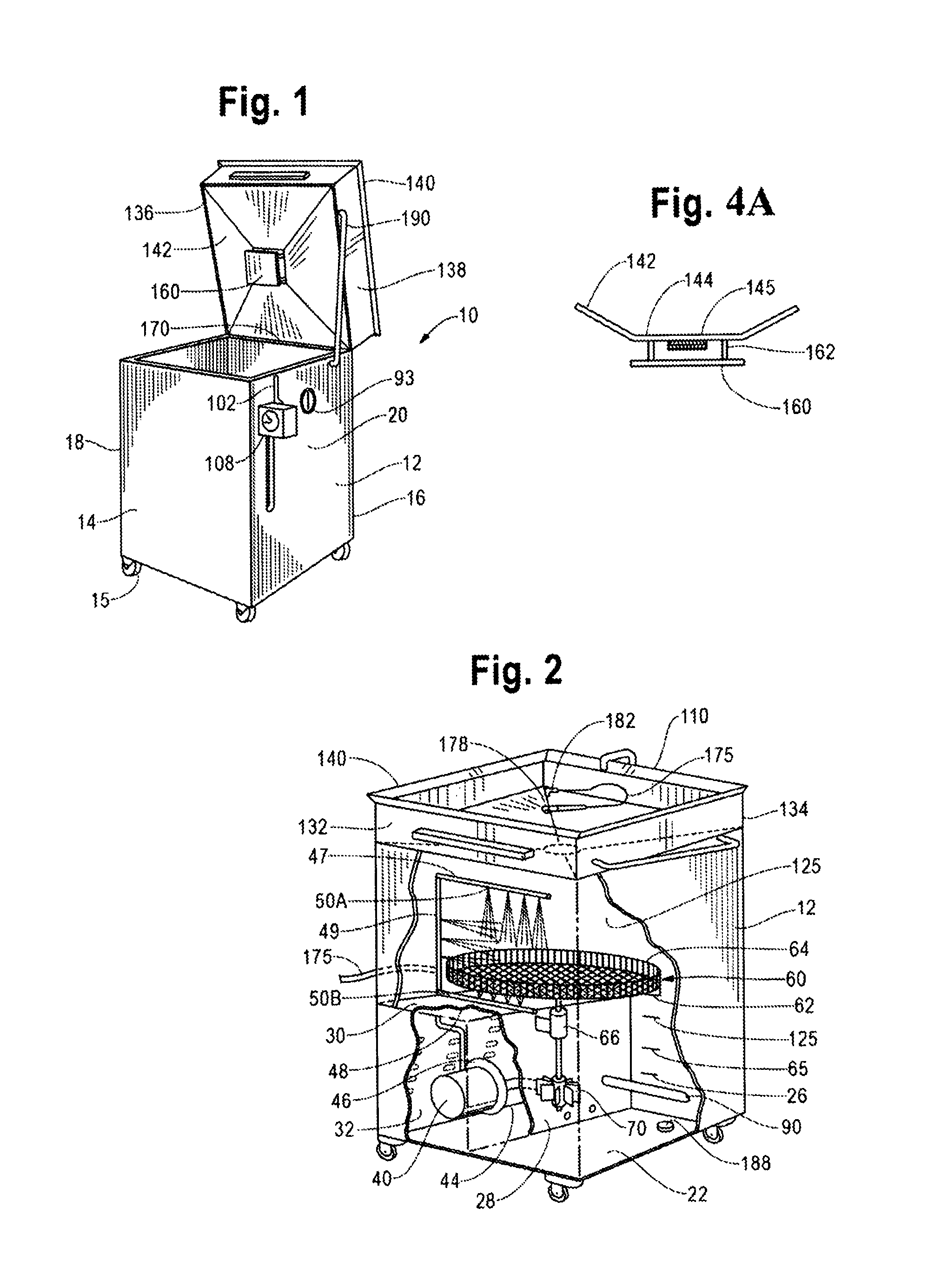
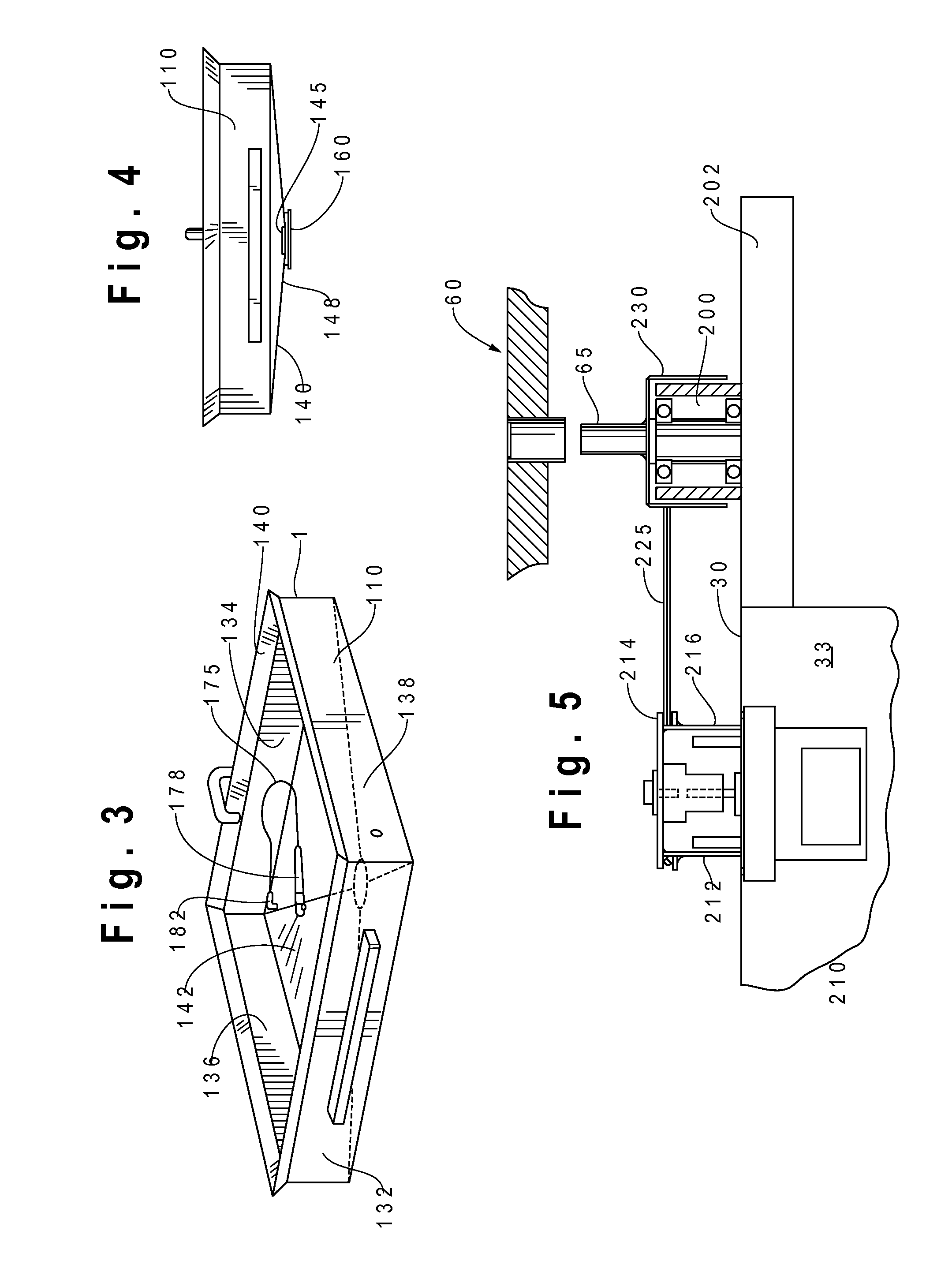
[0043]Turning now to the drawings, the parts washer of the present invention is generally designated by the numeral 10 and includes a lower cabinet generally designated by the numeral 12. The lower cabinet is shown as being generally square or rectangular in horizontal cross-section having front wall 14, rear wall 16 and opposite sidewalls 18 and 20. It will be apparent that the cabinet may be other shapes such as round. The cabinet has a floor 22 and defines a chamber having jet cleaning chamber 25 in its upper end and a fluid reservoir 26 in its lower end. A vertical panel 28 extends between the front wall 14 and rear wall 16. The upper edges of the panel connect to a horizontal panel 30 which defines a mechanical enclosure 32 which is accessible through a vented access door 34 in the sidewall 18. The enclosure 32 may be located at any convenient location in the cabinet. The cabinet 12 may be fabricated from a suitable material such as a 12 gauge, rolled steel which is preferably ...


PUM


Abstract

A multi-function parts washer for removing contaminants from parts either by hand or automatically using an aqueous cleaning fluid includes a base cabinet having sides, a floor and an open top defining a compartment. A parts receptacle is mounted in the compartment for receiving parts to be washed. The receptacle is mounted for reciprocating, vertical movement in the compartment. An agitator assembly includes one or more compressed gas bladders mounted to the parts receptacle. The bladder has an inlet for introducing compressed gas into the bladder and an outlet for discharge of the compressed gas from the bladder. As compressed gas is introduced into the bladder, the bladder inflates and the parts receptacle is raised, and as compressed gas is discharged from the bladder, the parts receptacle is lowered to provide an agitating motion of the parts receptacle and the parts thereon in the cleaning fluid. The agitator can include a hydraulic cylinder to effect movement of the parts receptacle.

Description

CROSS-REFERENCE TO RELATED APPLICATION DATA[0001]This application is a continuation-in-part of U.S. patent application Ser. No. 12 / 322,233, filed Jan. 29, 2009, which is a continuation-in-part of U.S. patent application Ser. No. 10 / 658,950, filed Sep. 9, 2003, now U.S. Pat. No. 7,484,515, incorporated herein by reference.BACKGROUND OF THE INVENTION[0002]The present invention relates to an apparatus for washing articles and more particularly relates to a combination agitating, vat-type and sink washer for washing articles such as automotive parts to remove grease, oil and other contaminants, preferably using a washing fluid which consists of a non-solvent based, non-flammable, biodegradable and environmentally acceptable washing solution.[0003]Various types of parts washers are commonly used in machine shops, garages, automotive shops and the like for removing the grime, oil and contamination from parts. In the past, most parts washers of the sink type utilized toxic cleaning fluids ...

Claims


Application Information

Patent Timeline
Patent Type & Authority Patents(United States)
IPC IPC(8): B08B3/00
CPCB08B3/006B08B3/02B08B3/10
Inventor LELE, ASHOK S.LISBERG, SCOTT D.HILLSTROM, THOMAS G.
Owner HERITAGE CRYSTAL CLEAN
Learn More