Cover for cable connectors

a technology for cables and connectors, applied in the direction of couplings/cases, coupling device connections, electrical devices, etc., can solve the problems of connectors, signal quality degradation, transmission line components such as connectors,

Active Publication Date: 2014-07-01
JOHN MEZZALINGUA ASSOC LLC
View PDF197 Cites 23 Cited by
  • Summary
  • Abstract
  • Description
  • Claims
  • Application Information

AI Technical Summary

Benefits of technology

[0010]It is therefore a principal object and advantage of the present invention to provide a cover for cable connectors or other components that may be quickly installed and / or removed.
[0011]It is another object and advantage of the present invention to provide a cable component cover that protects the cable connectors or other components from the environment.
[0012]It is yet another object and advantage of the present invention to provide a cable component cover that maintains its sealing properties regardless of temperature fluctuations.
[0013]It is a further object and advantage of the present invention to provide a cable connector cover that may be used in conjunction with other cable connector covers of various sizes and / or shapes.
[0014]Other objects and advantages of the present invention will in part be obvious, and in part appear hereinafter.
[0015]In accordance with the foregoing objects and advantages, a first aspect of the present invention provides a cover for a connector adapted to terminate a cable, wherein the connector includes a body portion and is adapted to terminate in a bulkhead. The cover comprises an elongated body comprising cable and bulkhead ends, interior and exterior surfaces, and the elongated body extends along a longitudinal axis. The interior surface includes a first region adapted to cover at least a portion of the cable and extends from the cable end to a first shoulder, wherein the first region is of a minimum, first cross-sectional diameter. The interior surface further includes a second region which is adapted to cover at least the connector body portion and which extends from the first shoulder to a second shoulder. The second region has a minimum, second cross-sectional diameter that is greater than the minimum, first cross-sectional diameter. The interior surface further includes a third region which is adapted to cover at least a portion of the connector and which extends from the second shoulder to the bulkhead end. The third region has a minimum, third cross-sectional diameter that is greater than the minimum, second cross-sectional diameter.

Problems solved by technology

Transmission line components such as connectors are often exposed to the open environment and are thus susceptible to degradation from weather related corrosive effects (e.g., moisture infiltration), pollution, debris and other elements.
Degradation of the components potentially leads to degradation of the signal quality being transmitted through the cables.
First, the taping requires significant time in its initial installation, and needs to be removed in order to gain access to the component when servicing the components (and then reapplied after servicing is complete). The time associated with the taping and removal thereof when servicing the components is costly. In addition, the quality of the seal is dependent on the skill of the worker that is applying the tape. As such, inconsistent application of the tape may lead to instances of ineffective sealing of components.
Second, the properties inherent in the material composition of the tape subjects the tape to size fluctuation and inconsistent adherence. If the tape contracts in colder temperatures and loses adherence strength in warmer temperatures, for example, the quality of the seal created through the tape becomes compromised in regions that experience wide temperature fluctuation. In addition, the same pollutants and other environmental factors that affect the components when unsealed may also affect the sealing quality of the tape.
While the opening and closing of the clamshell style cover facilitates quicker installation and removal in repair situations, it too is not without its drawbacks.
For instance, the plastic material becomes brittle in colder temperatures, and this reduction in ductility increases over time.
As the material becomes more brittle, the closure mechanisms lose their effectiveness often breaking or otherwise not reliably performing the closure function for which they were designed.
Furthermore, the clamshell style closures include seams that extend essentially the entire periphery of the cover, making the sealing function much more difficult when compared to covers that do not include such long seams between parts.
As such, the clamshell style covers lose their sealing effectiveness over time and in climates that routinely experience cold temperatures.

Method used


Image

  • Cover for cable connectors
  • Cover for cable connectors
  • Cover for cable connectors

Examples


fifth embodiment

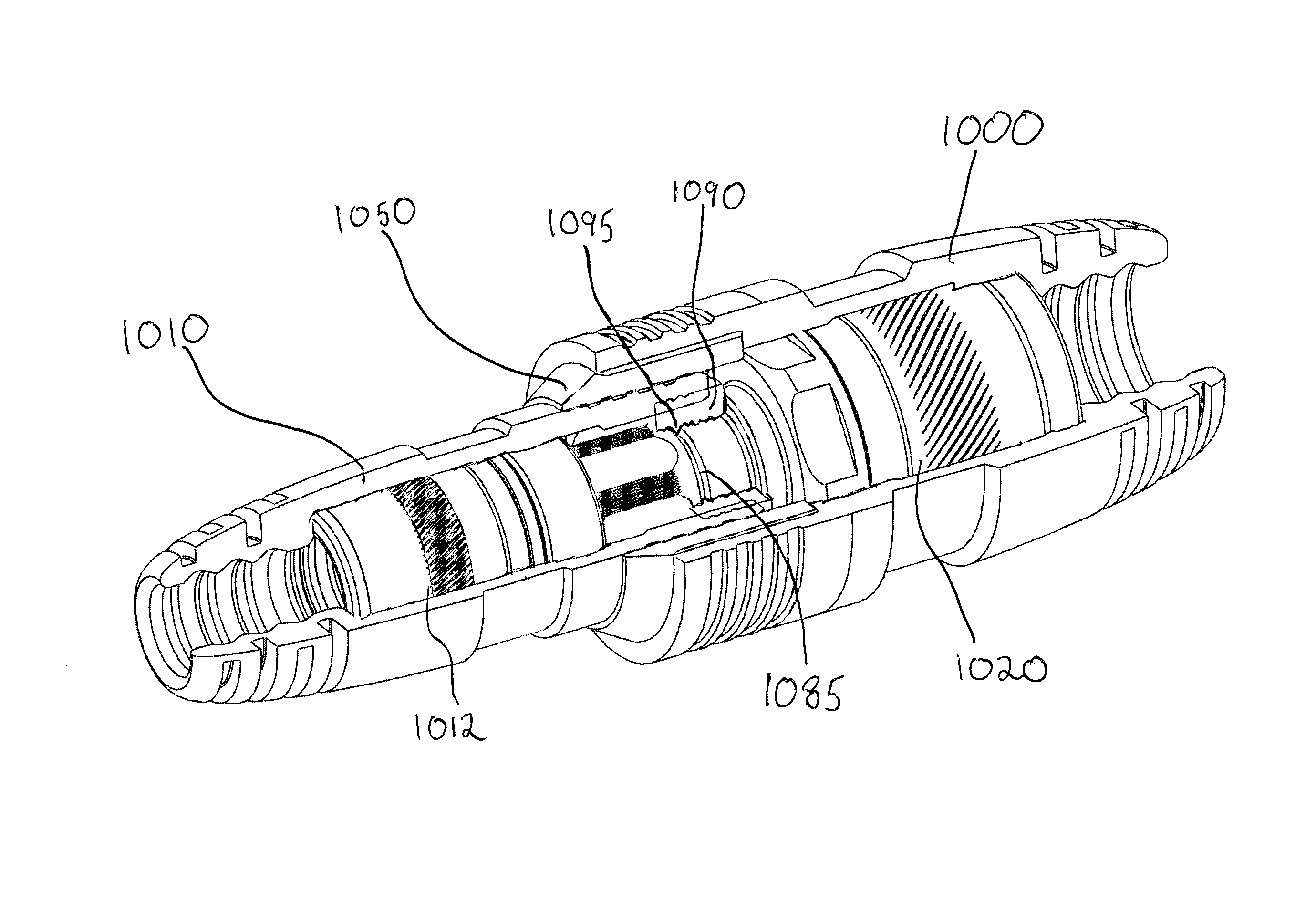
[0056]With further reference to the drawings, FIG. 12 depicts a partially cut-away perspective view of a system of covers 1000 and 1010 for providing cover to cable connections, such as connected cable connectors 1012 and 1020. The system embodiment may include an adaptor 1050, but other means may be utilized to space and seal the embodied covers and cover system. When connector 1012 is connected to connector 1020, there may be an annular depression 1085, or some other reduced-diameter axial length portion located where the external surfaces of the connectors 1012 and 1020 join, so that one portion of the a connector, such as connector 1020 is positioned within a portion of the other connector, such as 1012. The fifth cover embodiment may include a collar 1090, such as an elastomeric annular member having an internal protrusion 1095 configured so as to be located proximate where the connectors 1012 and 1020 join, so as to seal against the connectors. The collar 1090 may be configure...

sixth embodiment

[0059]As further shown with respect to the drawings, FIG. 16 depicts a cross-section view of a system of covers for providing cover to cable connections, such as a connector embodiment 2012 connected to a bulkhead connector port 2013. A cover 2010 may extend about the connector 2012 and a portion of the bulkhead 2013. A collar 2090 may be configured to reside between and form a seal against the cover 2010, the bulkhead connector 2013, and the connector 2012. Embodiments of the connector 2012 may have a coupler 2052 having a blend angle surface 2084. As such, embodiments of the collar 2090 may have a corresponding angled surface 2094. Moreover, a color 2090 may include an internal surface feature 2095 to help facilitate a seal against and between the connector 2012 and the bulkhead connector port. The internal surface feature may itself include angled or curved surfaces configured for mating with and forming a seal against the connected connector components.


PUM


Abstract

A cover and a system of covers for placement in sealed relation over a connector or a pair of connectors that is or are adapted to terminate a cable or splice together a pair of cables. The covers include a cable end that sealingly receives a cable therein, an elongated body that provides secure cover to a cable connector, and an end that abuts a bulkhead or sealingly engages with a second cover when used in a splicing application.

Description

CROSS-REFERENCE TO RELATED APPLICATIONS[0001]This application is a continuation in part application of and claims priority to U.S. application Ser. No. 13 / 723,859, filed Dec. 21, 2012, entitled “Cover for Cable Connectors, which is a continuation application of and claims priority to U.S. application Ser. No. 12 / 760,134, now U.S. Pat. No. 8,419,467 filed Apr. 14, 2010, entitled “Cover for Cable Connectors.”BACKGROUND OF THE INVENTION[0002]1. Field of the Invention[0003]The present invention relates to covers for cable connectors, and, more specifically, to covers that protect cable connectors from environmental degradation.[0004]2. Description of the Related Art[0005]Transmission line components such as connectors are often exposed to the open environment and are thus susceptible to degradation from weather related corrosive effects (e.g., moisture infiltration), pollution, debris and other elements. Degradation of the components potentially leads to degradation of the signal qualit...

Claims


Application Information

Patent Timeline
Patent Type & Authority Patents(United States)
IPC IPC(8): H01R13/52
CPCH01R13/5213H01R4/70
Inventor NATOLI, CHRISTOPHERMONTENA, NOAH
Owner JOHN MEZZALINGUA ASSOC LLC
Why Eureka
Try Eureka