
Modulating buttress saline mammary prosthesis including limpet fill port

a mammary prosthesis and module technology, applied in the field of preferably saline implants, can solve the problems of increasing the complication rate of implants, hardening what would otherwise be a soft breast, and scalding scar tissue, so as to improve the overall viscosity, enhance the performance, and improve the effect of viscosity

Inactive Publication Date: 2014-07-01
LEDERGERBER WALTER J
View PDF1 Cites 5 Cited by
  • Summary
  • Abstract
  • Description
  • Claims
  • Application Information

AI Technical Summary

Benefits of technology

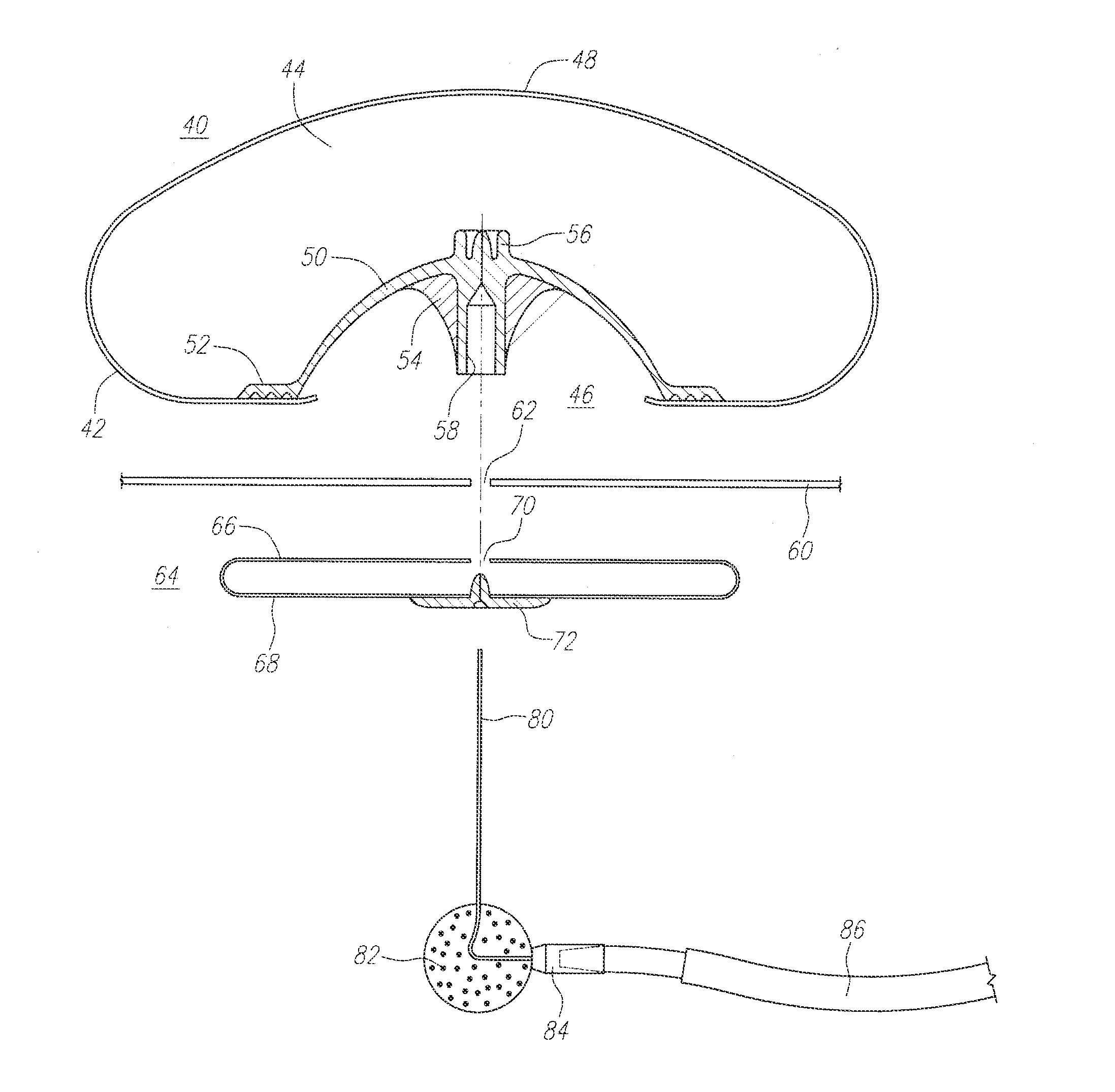
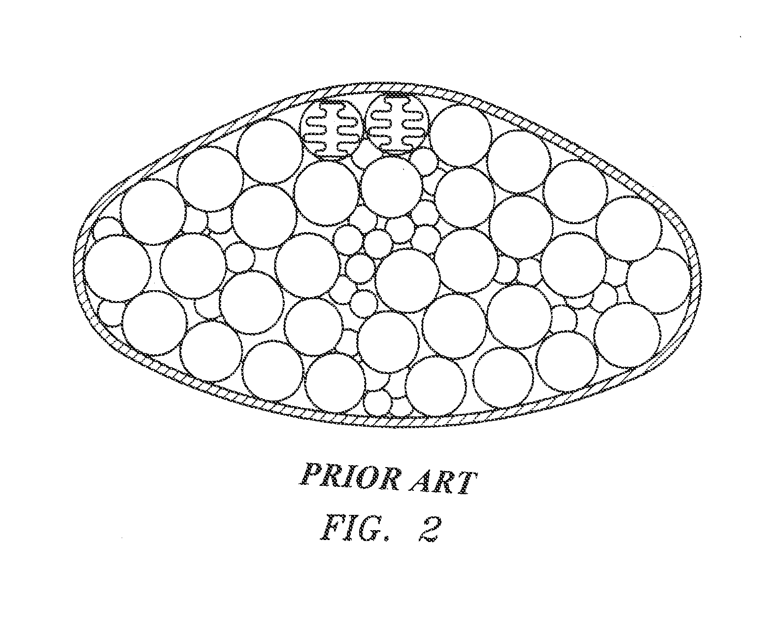
The invention is about an improved implantable mammary prosthesis that includes a shell and a slurry filler inside the shell. There is a fluid compartment in contact with the slurry filler and it can change its shape when pressure is applied. The fluid compartment is connected to a reservoir outside of the shell. The fluid compartment has a membrane to transfer the pressure from the slurry filler to the reservoir. The slurry has a higher viscosity due to its composition, which includes medical glass spheres or biocompatible polymer spheres. The slurry has a viscosity similar to toothpaste or bread dough. The invention aims to improve the performance and safety of the implantable mammary prosthesis.

Problems solved by technology

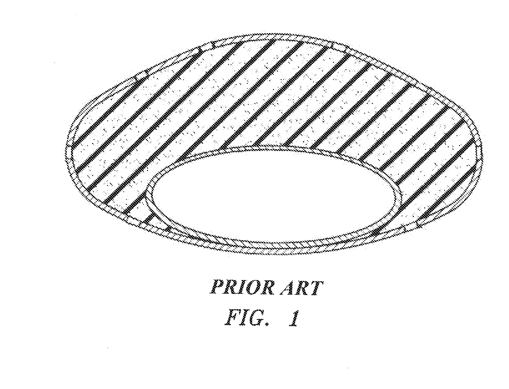
As a consequence, very dense tough scar tissue forms which serves to deform and severely harden what would otherwise be a soft breast.
Sub-muscular placement of implants has increased the complication rate.
Complex multi-component implant constructions including textured shells, “protective” saline compartmentalization around silicone gel compartments, and baffling schemes and others have been tried and eventually rejected as being problematic for a variety of reasons.
Unfortunately, resistance to its broad adoption has been based on esthetic consideration both ex vivo and as implanted.
Its acceptance has been limited by its less than satisfactory “off-clear” appearance, the propensity to wrinkle due to a stiff high density shell and the fact that normal saline filler itself offers little resistance to defamation and is too quick to propagate visible waves on deformation.
Such features have often led to embarrassment for the patient.

Method used


Image

  • Modulating buttress saline mammary prosthesis including limpet fill port
  • Modulating buttress saline mammary prosthesis including limpet fill port
  • Modulating buttress saline mammary prosthesis including limpet fill port

Examples


Embodiment Construction

[0020]The attached figures serve to illustrate the general and preferred embodiments of the invention. FIG. 3 shows a cross-section of the inventive implant in a general form. A shell 10 serves as the exterior surface of the implant. The shell 10 may be of a single material, or may be made of multiple layers (see, e.g., the embodiment of FIG. 4). Within the shell 10 is a slurry filler compartment 11 which is adapted to receive slurry filler 15 (shown enlarged in FIG. 6), or if the implant has been filled, will contain the slurry filler. The drawing of FIG. 3 and FIG. 4 only show a portion of the slurry filler for illustrative purposes, it being appreciated that the slurry filler would typically occupy the entirety of the slurry filler compartment 11 when fully filled. The slurry filler compartment 11 may either be an additional structure or may be the space defined by other structures such as the inside of the shell 10 and outside of the fluid compartment 13. A fluid compartment 13 ...


PUM


Abstract

An implantable mammary prosthesis includes a limpet buttress fill port structure. The fill port structure preferably comprises a shell, the shell including an opening, a compartment interior to the shell adapted to contain a filler. The limpet buttress is generally cup-shaped, and is disposed within the shell. The limpet buttress is preferably attached to the shell adjacent the opening to form a fluidic seal, optionally via a sealing flange. The limpet buttress may include one or more ribs, such as to provide structural support to the limpet buttress. Preferably, a reservoir is disposed external to the shell.

Description

PRIORITY CLAIM[0001]This application is a continuation-in-part application of U.S. Utility application Ser. No. 12 / 360,979, entitled “Modulating Buttress Saline Mammary Prosthesis”, filed Jan. 28, 2009, issued as U.S. Pat. No. 8,202,316 on Jun. 19, 2012, which application claims the benefit of and priority to U.S. Provisional patent application Ser. No. 61 / 024,405, entitled “Modulating Buttress Saline Mammary Prosthesis Gel Simulating Saline Implant”, filed Jan. 29, 2008, all hereby incorporated by reference as if fully set forth herein.FIELD OF THE INVENTION[0002]This invention relates to implantable prosthetic devices and to tissue expanders used in plastic and reconstructive surgery used to stretch tissues. More particularly, the invention relates generally to a preferably saline implant that simulates the properties of gel implants.BACKGROUND OF THE INVENTION[0003]Most tissue expanders and soft tissue-simulating implantable prostheses have been utilized to enhance or reconstruct...

Claims


Application Information

Patent Timeline
Patent Type & Authority Patents(United States)
IPC IPC(8): A61F2/12
CPCA61F2/12
Inventor LEDERGERBER, WALTER, J.
Owner LEDERGERBER WALTER J
Learn More