

Device for the contactless and nondestructive testing of surfaces
a non-destructive and surface technology, applied in the direction of radiation pyrometry, instruments, material analysis, etc., can solve the problems of large disadvantages of laser excitation, and affecting the accuracy of laser excitation results
Active Publication Date: 2014-07-01
WINTERTHUR INSTR
View PDF7 Cites 6 Cited by
- Summary
- Abstract
- Description
- Claims
- Application Information
AI Technical Summary
Benefits of technology
The invention is a device that uses light to non-destructively inspect surfaces. The device is easy to use and cost-effective. It has a wide area of intersection between the light that exits the device and the surface being tested, making it robust against changes in distance and tilting. The device has a compact construction and minimizes radiation losses. The excitation light is generated by LEDs, which can be arranged in a ring-shaped pattern to provide efficient energy utilization. The device can be used to test surfaces with specific spectral behavior.
Problems solved by technology
However, for applications outside a controlled protective environment, laser excitations suffer from major disadvantages.
Adequate precautions are therefore necessary and the measuring system can only be operated by trained personnel.
Moreover suitable laser excitations are relatively expensive.
Therefore increased expenditure has to be expected in conjunction with the purchase and operation of a testing equipment with laser excitation.
Apart from the disadvantages connected with using a laser source this arrangement has a further disadvantage: due to the shadow thrown by the reflecting mirror and due to the hole in the collecting lens part of the infrared radiation to be captured and emitted by the test piece gets lost.
Due to their spatially widespread radiation behaviour the major part of the excitation radiation is lost.
Therefore flash lamps are not very suitable as thermal excitation sources for the photo-thermal test procedure.
This lateral placement in turn has decisive disadvantages: the measuring device is spatially extended due to the parallel arrangement, and the radiation paths for excitation and detection cannot progress collinearly.
The flattened angle leads to losses during heating of the surface or / and to a more extensive measuring arrangement during detection of its detection radiation.
Method used
View moreImage
Smart ImageViewing Examples

Examples
first embodiment
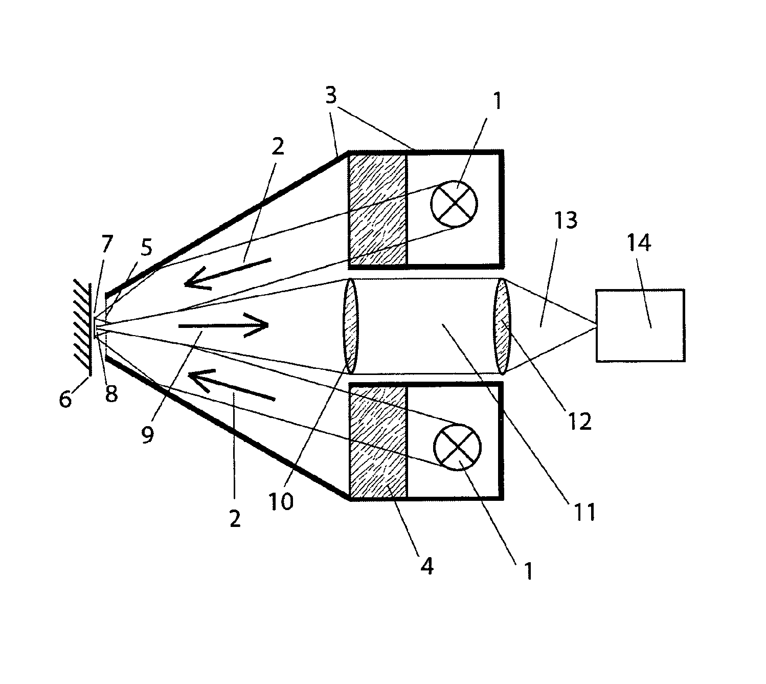
[0021]FIG. 1 shows a schematic sectional view through a device according to the invention;
second embodiment
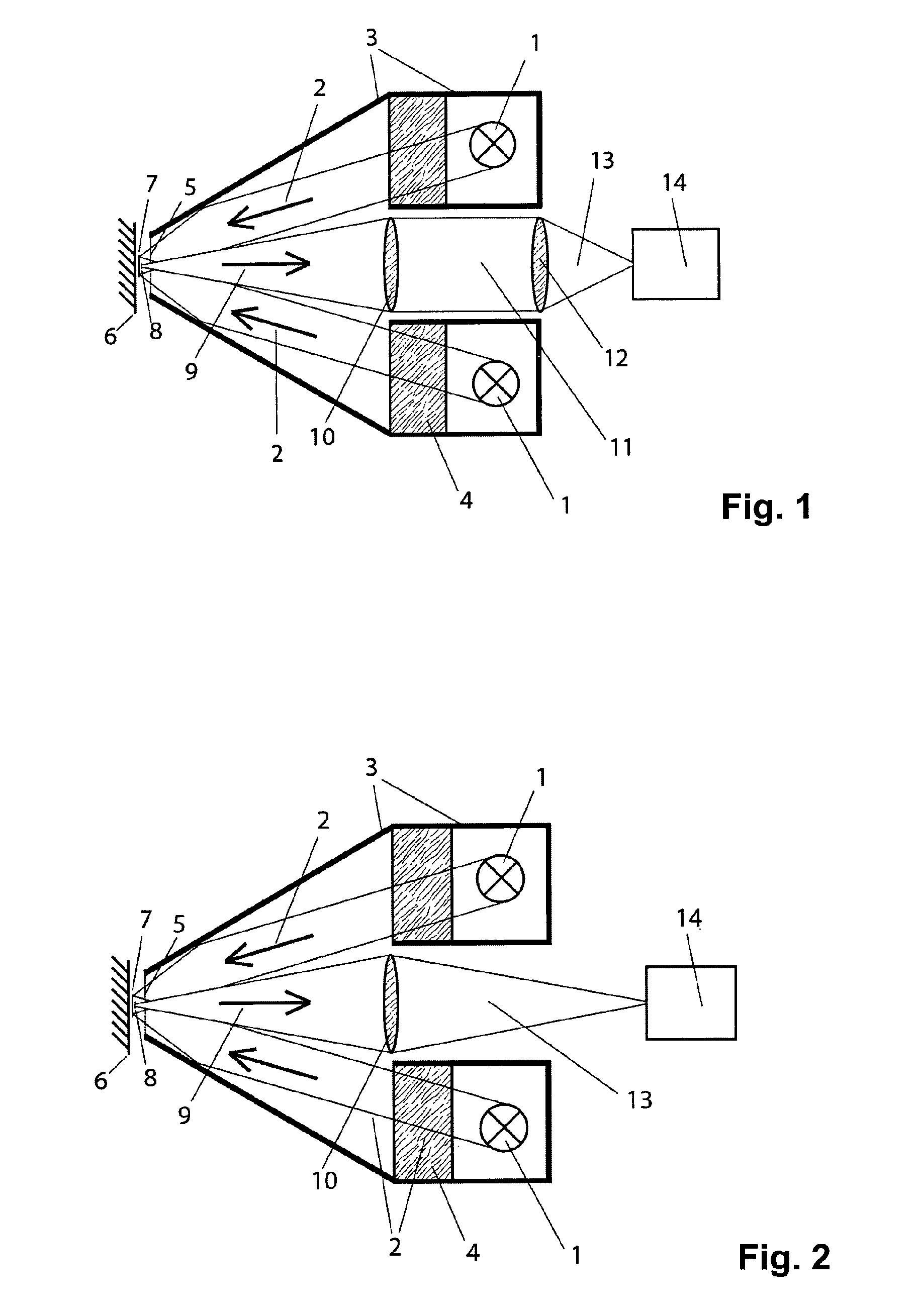
[0022]FIG. 2 shows a schematic sectional view through a device according to the invention;
third embodiment
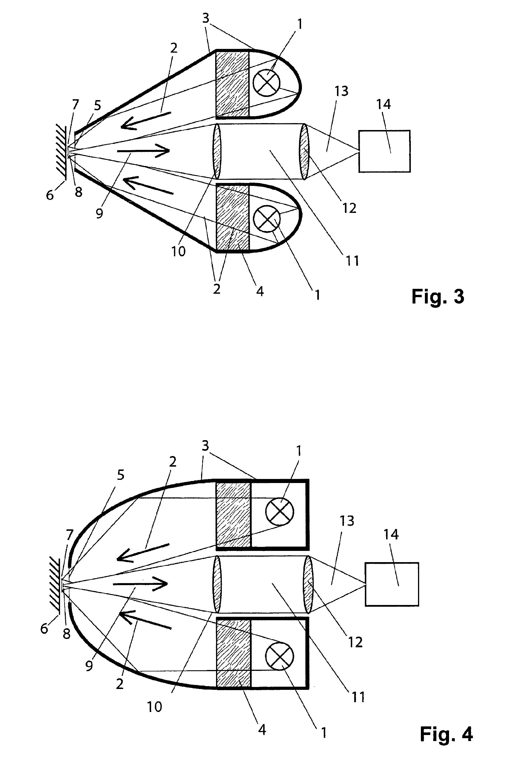
[0023]FIG. 3 shows a schematic sectional view through a device according to the invention;
Login to View More PUM
 Abstract
A device for the contactless and nondestructive testing of a surface by measuring the infrared radiation thereof has one or more incoherent electromagnetic radiation sources (1) and a detector (14) arranged on a detection axis (9), wherein the radiation sources (1) are arranged at a radial distance from the detection axis (9), at a distance from a testing area (7). In this arrangement, a pulsed or intensity-modulated excitation radiation (2) can be generated by these radiation sources (1) and applied to the surface (6) to be tested in the testing area (7) at an inclination to the detection axis (9) in the testing area (7). The detection radiation emitted by a measuring area (8) of the surface (6) to be tested can be fed to the detector (14), wherein the detector (14) is arranged on the detection axis (9) further away spatially from the testing area (7) than the radiation sources (1). Furthermore, an imaging device (10, 12) is provided on the detection axis (9) for creating an image of the testing area (7) on the measuring area of the detector (14) that is arranged between the radiation sources (1).
Description
CROSS REFERENCE TO RELATED APPLICATIONS[0001]This application is a National Stage of International Application No. PCT / CH2011 / 000097 filed May 2, 2011, claiming priority based on Swiss Patent Application No. 667 / 10, filed May. 3, 2010, the contents of all of which are incorporated herein by reference in their entirety.TECHNICAL FIELD[0002]The invention relates to a device for the contactless and non-destructive testing of a surface by measuring its infrared radiation.STATE OF PRIOR ART[0003]The contactless testing of surfaces based on the generation and measurement of transient or periodic heating and cooling processes requires an excitation source for heating the surface to be tested as well as an infrared detector which measures the infrared radiation emitted from the heated surface. This method is called photothermy if electromagnetic radiation in the ultra-violet, optical or infrared range is used for excitation. The excitation radiation may for example come from the back of a s...
Claims
Login to View More Application Information
Patent Timeline
 Patent Type & AuthorityPatents(United States)
IPC IPC(8): G01J5/02
CPCG01N21/84G01N21/55G02B19/0085G02B19/0028G01N25/72G02B19/009G01B21/085
InventorREINKE, NILSBARISKA, ANDOR
OwnerWINTERTHUR INSTR