
Corrugated strap for securing a heat exchanger

Active Publication Date: 2014-07-08
DEERE & CO
View PDF11 Cites 4 Cited by
  • Summary
  • Abstract
  • Description
  • Claims
  • Application Information

AI Technical Summary

Benefits of technology

[0003]Disclosed is a power system comprising a mount, a heat exchanger, and a corrugated strap positioned about the heat exchanger for securing the heat exchanger to the mount. The heat exchanger comprises a separation edge, and the corrugated strap may comprise a first corrugated section and a second corrugated section. A separation bend may be

Problems solved by technology

Because the dimensions of the heat exchanger may vary, a strap that effectively secures one heat exchanger may not effectively secure another.
Plus, even if the strap does effectively secure a specific heat

Method used


Image

  • Corrugated strap for securing a heat exchanger
  • Corrugated strap for securing a heat exchanger
  • Corrugated strap for securing a heat exchanger

Examples


Example

DETAILED DESCRIPTION OF THE DRAWINGS

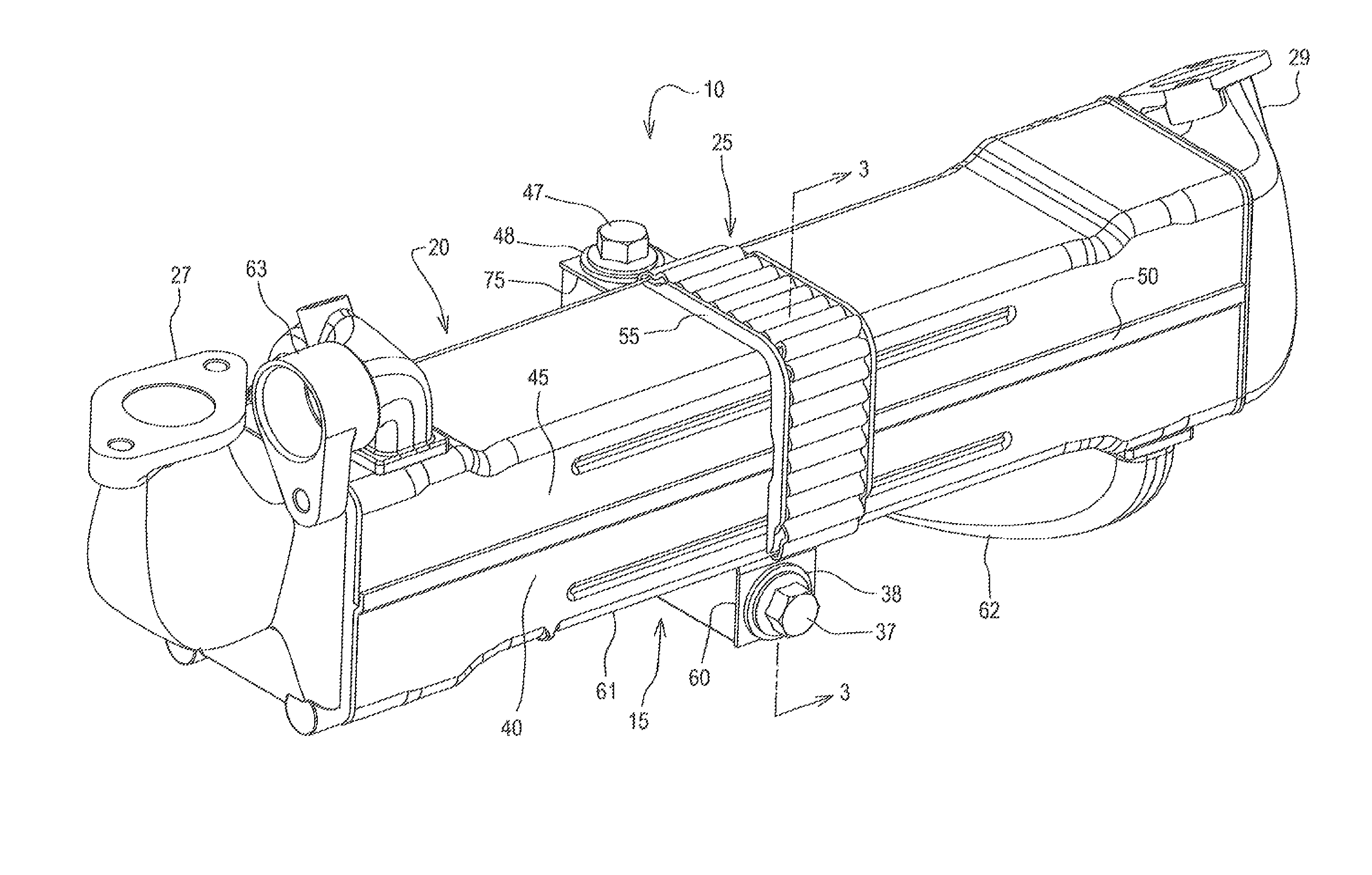
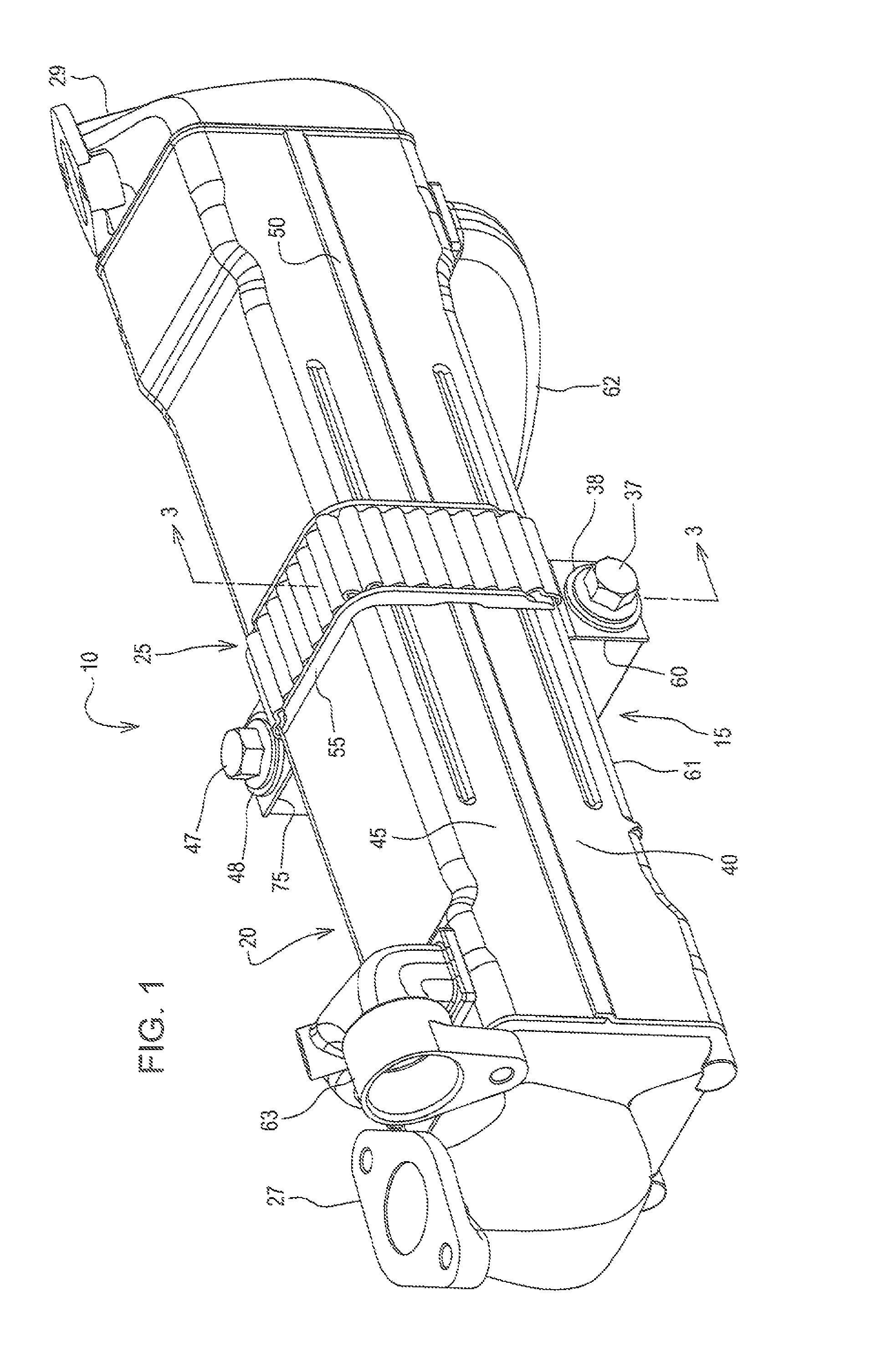
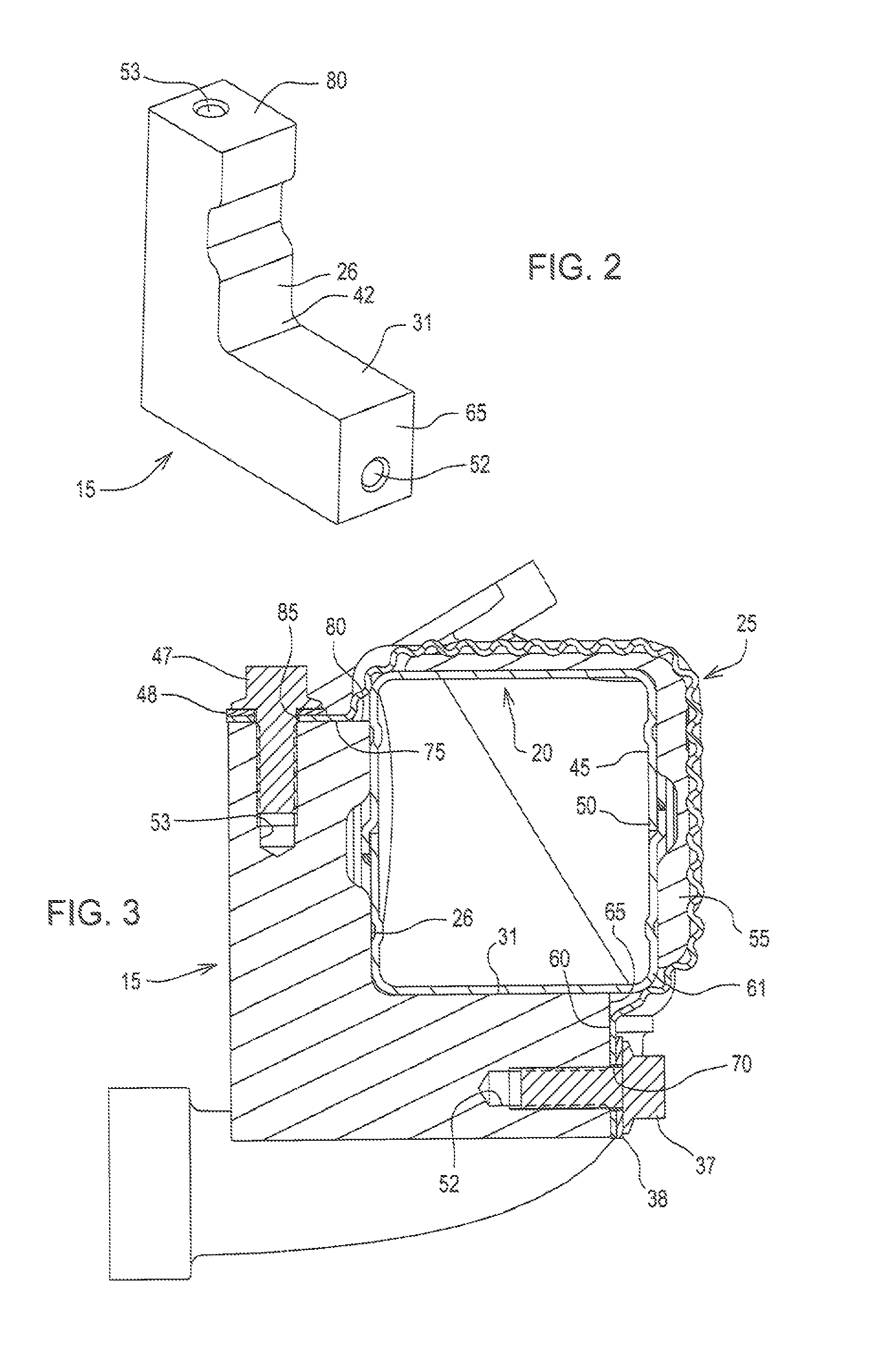
[0010]Referring to FIG. 1 and FIG. 2, there is shown a power system 10 comprising a mount 15, a heat exchanger 20, and a first corrugated strap 25 positioned about the heat exchanger 20 for securing the heat exchanger 20 to the mount 15. The number of first corrugated straps 25 used in a given application (i.e., one or more) may depend on the length and weight of the heat exchanger 20. The heat exchanger 20 may be, for example, an exhaust gas recirculation cooler (EGR cooler) for cooling exhaust gas.

[0011]The power system 10 may further comprise an engine (not shown), and the mount 15 may be secured to the engine. The engine may be, for example, a diesel engine or a gas engine. Exhaust gas from the engine may enter the heat exchanger 20, via an exhaust gas inlet 27, and the exhaust gas may then exit the heat exchanger 20, via an exhaust gas outlet 29, and be rerouted back to the engine. Engine coolant may enter, via a coolant inlet 62, and exit th...


PUM


Abstract

Disclosed is a power system comprising a mount, a heat exchanger, and a corrugated strap positioned about the heat exchanger for securing the heat exchanger to the mount. The heat exchanger comprises a separation edge, and the corrugated strap may comprise a first corrugated section and a second corrugated section. A separation bend may be positioned between the first corrugated section and the second corrugated section, and the separation bend may overlap the separation edge.

Description

FIELD OF THE DISCLOSURE[0001]The present disclosure relates to a power system. More specifically, the present disclosure relates to a power system comprising a corrugated strap positioned about a heat exchanger for securing it to a mount.BACKGROUND OF THE DISCLOSURE[0002]In known power systems, a strap may be used to secure a heat exchanger to a mount. Because the dimensions of the heat exchanger may vary, a strap that effectively secures one heat exchanger may not effectively secure another. Plus, even if the strap does effectively secure a specific heat exchanger, the strap may become too tight, during operation, as the heat exchanger thermally expands, and it may become too loose as the heat exchanger thermally contracts (i.e., varying clamping forces). What is needed is a strap that overcomes these challenges.SUMMARY OF THE DISCLOSURE[0003]Disclosed is a power system comprising a mount, a heat exchanger, and a corrugated strap positioned about the heat exchanger for securing the...

Claims


Application Information

Patent Timeline
IPC IPC(8): F02B47/08F02B47/00
CPCF28F9/002F02M25/0737F28D21/0003F28D2021/0082F28F9/007F28F9/013F28F2275/08F28F2275/085Y02T10/121F02M26/32
Inventor KRGO, AHMOWATKINS, BRADLEY R.TAUTE, MARK A.
Owner DEERE & CO
Learn More