
Ejection self-adaption tail base advancement system

An adaptive and tailstock technology, which is applied in the direction of tailstock/top, tool holder accessories, turning equipment, etc., can solve problems such as wasting energy, reducing the service life of hydraulic pumps, and limiting the width of machine tool guide rails

Active Publication Date: 2019-12-24
YANGTZE NORMAL UNIVERSITY
View PDF11 Cites 2 Cited by
  • Summary
  • Abstract
  • Description
  • Claims
  • Application Information

AI Technical Summary

Problems solved by technology

[0002] The existing tailstock can realize position programming by adding screw drive, or realize position programming by dragging the bed saddle, but the jacking force of the tailstock is provided by the hydraulic cylinder, and the adjustment of the pressure needs to be manually adjusted. It is inconvenient to adjust the hydraulic pressure. If the information provided by the manufacturer is incomplete, the workers need to calculate the jacking force by themselves, which takes a long time to set up and auxiliary processing time.
[0003] The jacking force of the existing tailstock is generally realized by a hydraulic cylinder. Although the jacking force can be kept unchanged in theory, the pressure of the hydraulic system fluctuates and is not stable enough, and the hydraulic pump needs to work continuously to maintain the hydraulic pressure. Wastes energy and cuts hydraulic pump life
[0004] After the existing tailstock is locked in place, the small oil cylinder piston exerts positive pressure on the guide rail of the machine tool to generate friction to achieve the purpose of locking the tailstock. This locking method has low reliability, especially when a large friction force is required. , under the conditions of the limited volume of the tailstock, the limited width of the guide rail of the machine tool, and the limited maximum pressure of the hydraulic system of the machine tool, it is impossible to generate sufficient friction
Similarly, maintaining the hydraulic pressure in the oil cylinder requires the hydraulic pump to work continuously, which wastes energy and reduces the service life of the hydraulic pump.
[0005] At the same time, after the tailstock tightens the workpiece and cuts it, the workpiece is heated by cutting friction and produces axial elongation deformation. This deformation will cause a slight movement of the tip of the tailstock in the opposite direction, resulting in the tip not being able to continuously and reliably press the workpiece. This small The change will affect the processing accuracy of the workpiece, so it is necessary to design a top tight adaptive tailstock travel system to solve this problem

Method used


Image

  • Ejection self-adaption tail base advancement system
  • Ejection self-adaption tail base advancement system
  • Ejection self-adaption tail base advancement system

Examples


Embodiment Construction

[0019] The present invention will be described in further detail below in conjunction with the accompanying drawings.

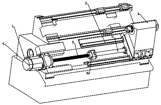
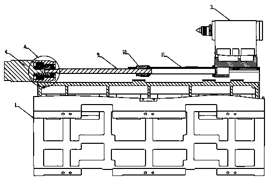
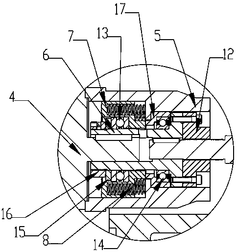
[0020] For specific implementation: see Figure 1 to Figure 3 , a top-tight self-adaptive tailstock travel system, including a guide rail 2 installed on the machine bed 1, a tailstock 3 slidably arranged on the guide rail 2, and a drive that is connected with the tailstock 3 and drives it to move on the guide rail mechanism, the drive mechanism includes a servo motor 4, a mounting seat 5, and a flange coupling front cover 6, the mounting seat 5 is fixedly arranged on the bed 1, and the flange coupling front cover 6 can be moved through a bearing Rotation is installed in the through hole opened in the axial direction of the mounting base 5, the output shaft of the servo motor 4 is inserted in the front end of the front sleeve 6 of the flange coupling and rotates with it, the flange coupling The rear end of the front sleeve 6 of the device is connected with th...


PUM


Abstract

The invention discloses an ejection self-adaption tail base advancement system. The system comprises a guide rail mounted on a machine body of a machine tool, a tail base slidingly arranged on the guide rail, and a driving mechanism connected with the tail base and driving the tail base to move on the guide rail; the driving mechanism comprises a servo motor, a mounting base and a flange coupling;the mounting base is fixedly arranged on the machine body; the flange coupling is directly connected with a motor shaft and a rod end of a lead screw; a front cover of the flange coupling is providedwith a deep groove ball bearing for rotary supporting; and an output shaft of the servo motor and the end part of the lead screw are mounted in the front cover of the flange coupling through a key connecting mode for synchronous rotation, and drive the tail base to linearly move on the guide rail by a spiral transmission mode. The system can guarantee stable workpiece machining precision, achieves a tail base ejection self-adaption effect, can reduce machining errors, and improves the machining precision.

Description

technical field [0001] The invention belongs to the technical field of machine tools, and in particular relates to a jacking and self-adaptive tailstock traveling system. Background technique [0002] The existing tailstock can realize position programming by adding screw drive, or realize position programming by dragging the bed saddle, but the jacking force of the tailstock is provided by the hydraulic cylinder, and the adjustment of the pressure needs to be manually adjusted. It is inconvenient to adjust the hydraulic pressure. If the information provided by the manufacturer is incomplete, the workers need to calculate the jacking force by themselves, which takes a long time to set up and auxiliary processing time. [0003] The jacking force of the existing tailstock is generally realized by a hydraulic cylinder. Although the jacking force can be kept unchanged in theory, the pressure of the hydraulic system fluctuates and is not stable enough, and the hydraulic pump need...

Claims


Application Information

Patent Timeline
IPC IPC(8): B23B23/00B23B33/00
CPCB23B23/00B23B33/00
Inventor 姜魏梁
Owner YANGTZE NORMAL UNIVERSITY
Learn More