Numerical control clamp capable of being fast assembled and disassembled

A fixture, assembly and disassembly technology, applied in the field of mechanical processing, can solve the problems that are difficult to meet the needs of modern enterprise production, affect the production efficiency and processing quality of parts, and the processing size is out of tolerance. The effect of clamping and positioning with high precision

Pending Publication Date: 2019-05-31
ZHONGSHAN POLYTECHNIC
View PDF0 Cites 1 Cited by
  • Summary
  • Abstract
  • Description
  • Claims
  • Application Information

AI Technical Summary

Problems solved by technology

[0003] CNC machining of cylindrical parts is very common in actual production. Because the shape of such parts is cylindrical, ordinary vise fixtures in processing cannot meet the installation of such parts. In order to solve the problem of cylindrical parts installation, two V The method of matching the shape block with the vise to tighten the workpiece
[0004] However, this traditional method not only takes a long time for clamping, but also the position of the part will change every time it is clamped, which leads to the need to re-set the tool every time in NC machining, and it is easy to cause tool setting errors in mass production, which will cause machining Oversize
Therefore, the use of ordinary fixtures for cylindrical parts will seriously affect the production efficiency and processing quality of such parts, and it is difficult to meet the needs of modern enterprise production.

Method used


Image

  • Numerical control clamp capable of being fast assembled and disassembled
  • Numerical control clamp capable of being fast assembled and disassembled
  • Numerical control clamp capable of being fast assembled and disassembled

Examples


Embodiment Construction

[0046] In order to make the purpose, technical solutions and advantages of the embodiments of the present invention clearer, the technical solutions in the embodiments of the present invention will be clearly and completely described below in conjunction with the drawings in the embodiments of the present invention. Obviously, the described embodiments It is a part of embodiments of the present invention, but not all embodiments. The components of the embodiments of the invention generally described and illustrated in the figures herein may be arranged and designed in a variety of different configurations.

[0047] Accordingly, the following detailed description of the embodiments of the invention provided in the accompanying drawings is not intended to limit the scope of the claimed invention, but merely represents selected embodiments of the invention. Based on the embodiments of the present invention, all other embodiments obtained by persons of ordinary skill in the art wi...


PUM


Abstract

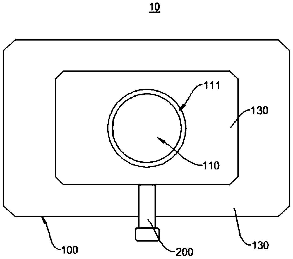
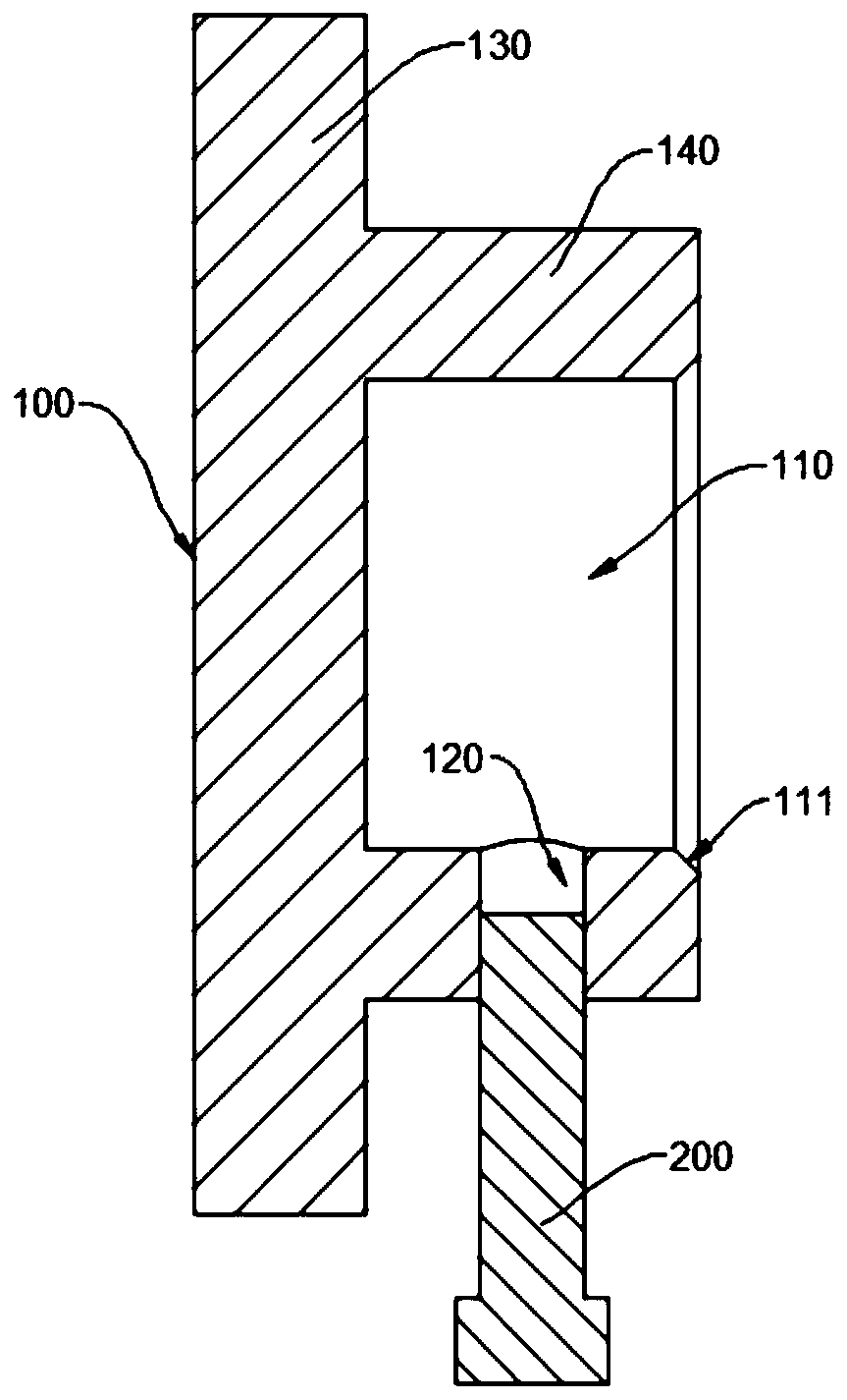
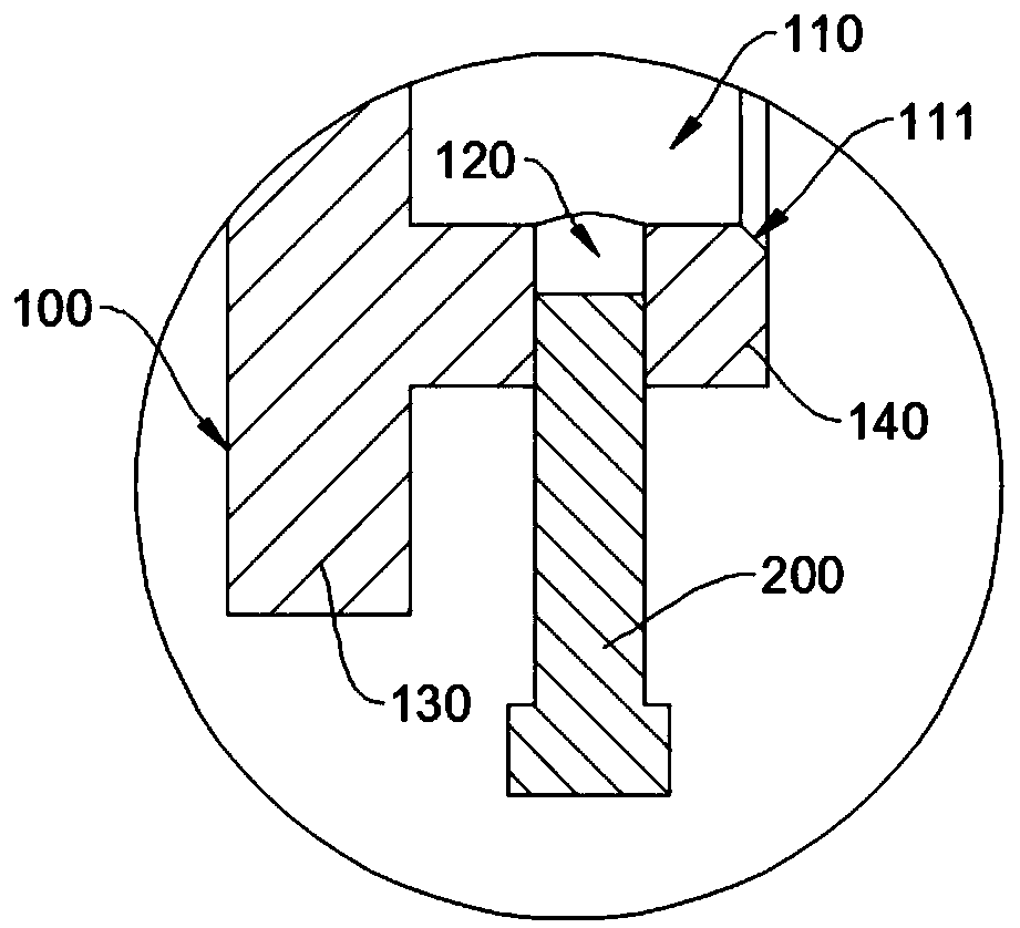
The invention relates to the technical field of machining, in particular to a numerical control clamp capable of being fast assembled and disassembled. The numerical control clamp capable of being fast assembled and disassembled is used for clamping a cylindrical part, and comprises a clamp body and a fastener; the clamp body is provided with a cylindrical first groove, and the inner wall of the first groove is provided with a through first through hole; the first through hole extends in the radial direction of the first groove; the fastener is arranged in the first through hole in a penetrating manner; the inner diameter of the first groove is equivalent to the outer diameter of the cylindrical part, and the first groove is arranged to contain the cylindrical part; the fastener is arranged to fasten the cylindrical part in the first groove; and the clamp body is arranged to be arranged on a machine tool workbench. During numerical control machining, the cylindrical part can be fast and conveniently assembled and disassembled, and the workpiece clamping difficulty is lowered; the positioning precision of the part is improved much than the positioning precision achieved through a universal clamp, and the positioning error of the part can be reduced; and during batch production, it is only needed to disassemble and assemble a workpiece, tool setting operation is not needed to beperformed again, and the auxiliary operation time can be substantially shortened.

Description

technical field [0001] The invention relates to the technical field of mechanical processing, in particular to a numerically controlled fixture that can be quickly assembled and disassembled. Background technique [0002] CNC machining plays an important role in the machinery manufacturing industry, and fixtures for CNC machining play a very important role in mass-produced parts. [0003] CNC machining of cylindrical parts is very common in actual production. Because the shape of such parts is cylindrical, ordinary vise fixtures in processing cannot meet the installation of such parts. In order to solve the problem of cylindrical parts installation, traditionally two V The method of cooperating the shaped block with the vise is used to tighten the workpiece. [0004] However, this traditional method not only takes a long time for clamping, but also the position of the part will change every time it is clamped, which leads to the need to re-set the tool every time in NC mach...

Claims


Application Information

Patent Timeline
Patent Type & Authority Applications(China)
IPC IPC(8): B23Q3/06B23Q3/18
Inventor 肖军民
Owner ZHONGSHAN POLYTECHNIC
Why Eureka
Try Eureka