
Servo drive traction machine

A technology of servo drive and traction machine, which is applied in the field of mechanical devices, can solve the problems of difficult adjustment and quantification of clamping force, inability to achieve self-adaptive constant clamping force, unstable production line speed, etc., so as to facilitate the adjustment of clamping pressure , convenient adjustment, better consistency of up and down traction

Inactive Publication Date: 2018-04-24
NANJING ORIENTLEADER TECH CO LTD
View PDF5 Cites 3 Cited by
  • Summary
  • Abstract
  • Description
  • Claims
  • Application Information

AI Technical Summary

Problems solved by technology

The clamping of the existing equipment is often adjusted by the hand handle, the clamping force is difficult to adjust and quantify, and the speed of the production line is unstable, especially in the initial production line start-up and speed-up stages, and when faced with changes in the appearance and size of the product during the production process, it is impossible to do so. to Adaptive Constant Gripping Force

Method used


Image

  • Servo drive traction machine
  • Servo drive traction machine
  • Servo drive traction machine

Examples


Embodiment Construction

[0020] The present invention will be described in detail below in conjunction with the accompanying drawings and specific embodiments.

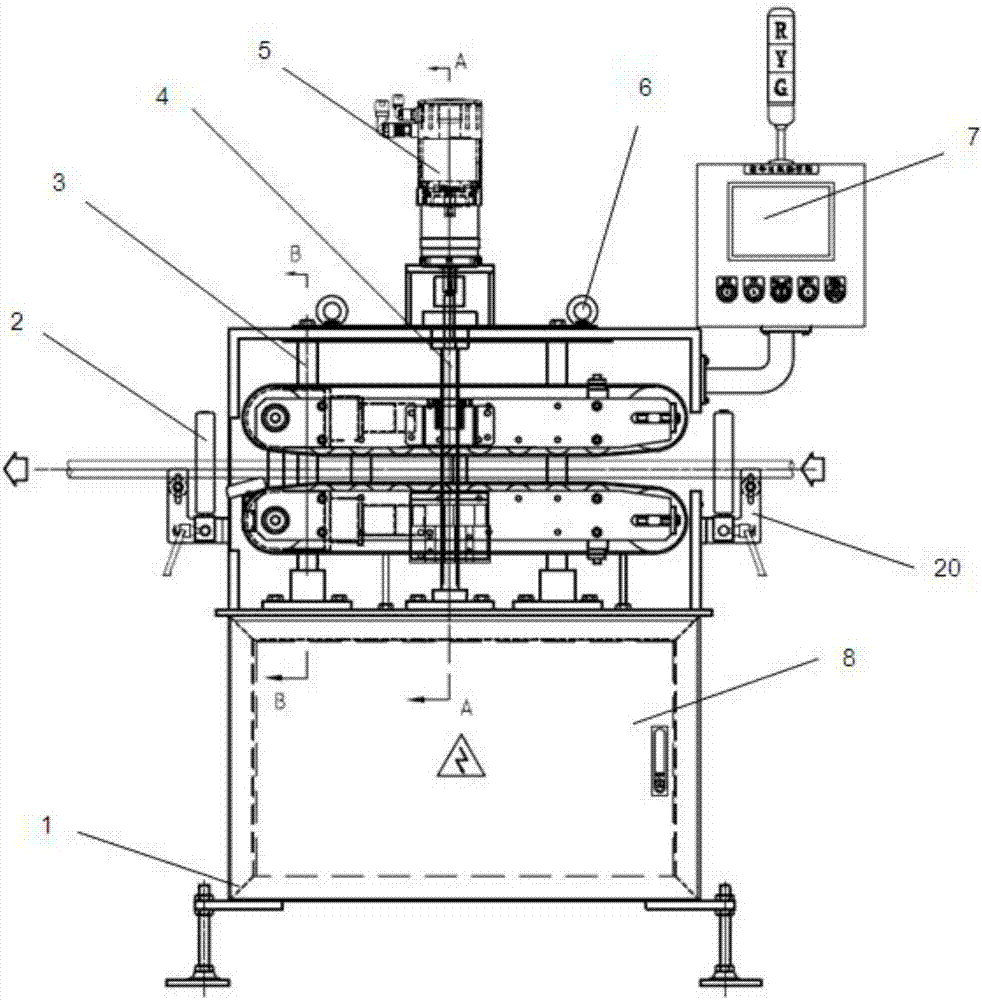
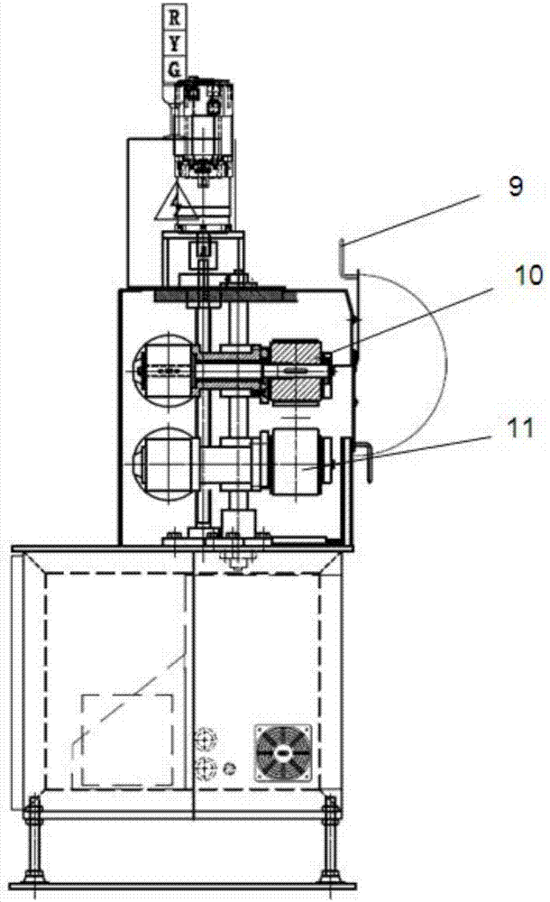
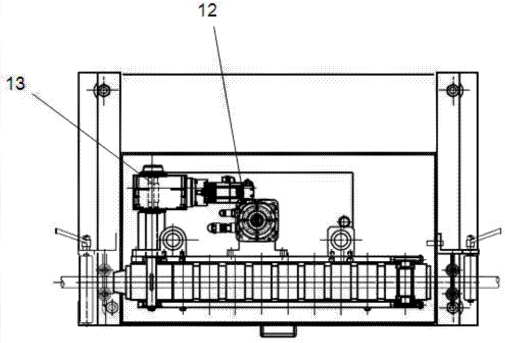
[0021] Such as Figures 1 to 5 As shown, a servo-driven tractor includes a frame 1, and an electric box 8, an operation box 7 and a transmission mechanism arranged on the frame 1, and the transmission mechanism includes a linear polished rod 3, a screw rod 4, an opening and closing servo Motor 5, upper side traction 10, lower side traction 11, driving servo motor 12 and reduction box 13, the linear polished rod 3 is connected with the upper side traction 10, lower side traction 11 through linear bearings 18, the opening and closing servo motor 5 Connected with the screw 4, the upper side traction 10 and the lower side traction 11 are installed on the side of the screw 4 through the nut 14 and the nut seat 15, and the cylinder 16 is also connected between the lower side traction 11 and the nut seat 15, and the opening and closing servo motor 5...


PUM


Abstract

The invention discloses a servo drive traction machine. The servo drive traction machine comprises a machine frame, an electric box, an operation box and a transmission mechanism, wherein the electricbox is arranged on the machine frame. The transmission mechanism comprises a linear polish rod, a screw rod, an opening and closing servo motor, an upper side traction device, a lower side traction device, a driving servo motor and a reduction gearbox, wherein the linear polish rod is connected with the upper side traction device and the lower side traction device through a linear bearing, the opening and closing servo motor is connected with the screw rod, the lower side traction device and the lower side traction device are installed on the side part of the screw rod through a nut and a nutseat, an air cylinder is further connected between the lower side traction device and the nut seat, and the air cylinder is driven by the opening and closing servo motor to provide the transaction opening and closing power for the upper side traction device and the lower side traction device. A belt pulley of the upper side traction device and a belt pulley of the lower side traction device provide the driving power by the driving servo motor and the reduction gearbox, the belt pulleys drive belts to carry out traction, and guide mechanisms are further arranged at the two ends of the upper side traction device and the lower side traction device. According to the servo drive traction machine, the clamping pressure is conveniently adjusted, the constant clamping force can be provided, and the stable wire production speed can be provided.

Description

technical field [0001] The invention belongs to the technical field of mechanical devices, and belongs to traction equipment for extrusion production lines of pipe products, in particular to a servo-driven traction machine. Background technique [0002] With the rapid development of the domestic economy, especially the rapid development of the automobile industry and high-speed rail, rubber hoses have become an indispensable material in daily life and industrial development. In the production process of rubber hose extrusion, the traction equipment is very important. It must not only ensure that the product is not crushed during the production process, but also ensure that it can provide sufficient and stable traction. The clamping of the existing equipment is often adjusted by the hand handle, the clamping force is difficult to adjust and quantify, and the speed of the production line is unstable, especially in the initial stage of production line start-up and speed-up, and...

Claims


Application Information

Patent Timeline
Patent Type & Authority Applications(China)
IPC IPC(8): B29C47/34B29C47/92B29L23/00B29C48/355B29C48/92
CPCB29C48/92B29C48/355B29C2948/92514B29C2948/92933B29L2023/22
Inventor 马逵崔龙奇徐小龙
Owner NANJING ORIENTLEADER TECH CO LTD
Learn More