Low-loss material dielectric property measurement device adopting split-cylinder resonator method

A technology for measuring dielectric properties and measuring devices, which is applied in the field of low-loss material dielectric properties measuring devices by split cylindrical resonant cavity method, can solve the problem of material types, poor size adaptability, limited adjustment range of micrometer pressing force, and resonant cavity. Alignment accuracy is difficult to guarantee and other problems, so as to improve the convenience of use and measurement efficiency, the clamping force is constant, and the size adaptability is improved.

Active Publication Date: 2015-01-21
CHINA ELECTRONIS TECH INSTR CO LTD
View PDF7 Cites 2 Cited by
  • Summary
  • Abstract
  • Description
  • Claims
  • Application Information

AI Technical Summary

Problems solved by technology

[0007] For the device used in the laboratory to fix the two resonant cavities by bolts, because the two split resonant cavities need to be manually adjusted for alignment, the measurement consistency is poor, the efficiency is low, and it is inconvenient to use
It is only suitable for simple application in the laboratory, and it is difficult to carry out product promotion
[0008] A material dielectric property measurement device based on a micrometer is usually fixed with one of the resonant cavities (moving cavity) and the spiral micrometer rod of the micrometer. The overall structure of the measurement device is limited by the structure of the micrometer, and the adjustment range of the pressing force of the micrometer Limited, poor adaptability to the material type and size of the sample to be tested
In addition, there is a transmission gap in the micrometer screw of the micrometer. Under the action of the self-weight of the movable cavity, it is difficult to ensure the alignment accuracy of the two resonant cavities, which in turn affects the measurement accuracy.

Method used


Image

  • Low-loss material dielectric property measurement device adopting split-cylinder resonator method
  • Low-loss material dielectric property measurement device adopting split-cylinder resonator method
  • Low-loss material dielectric property measurement device adopting split-cylinder resonator method

Examples


Embodiment 1

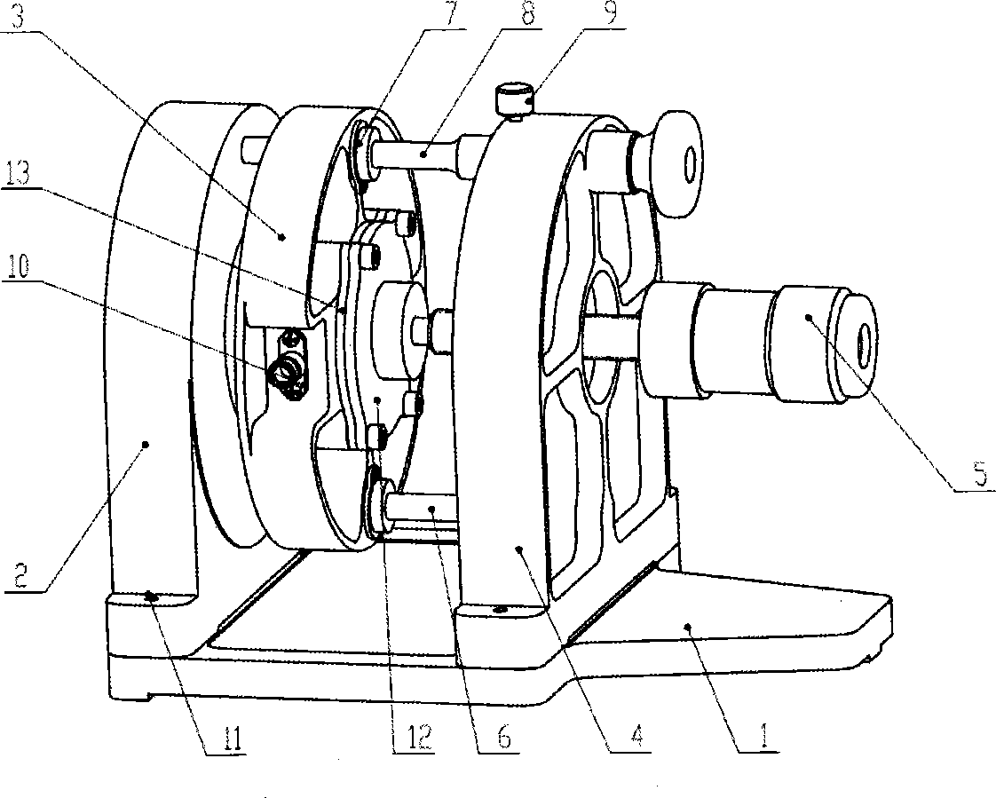
[0032] figure 2 Shown is the overall structure of a device for measuring the dielectric properties of low-loss materials by the split cylindrical resonator method of the present invention. It mainly consists of base plate 1, fixed cavity 2, movable cavity 3, support base 4, torque handle 5, lower guide rod 6, precision linear bearing 7, upper guide rod 8, locking screw 9, coaxial connector 10, positioning pin 11, connecting plate 12, protective plate 13, stopper are formed. During the measurement process, the sample to be tested is clamped between the fixed cavity 2 and the movable cavity 3, and the torque handle 5 is turned, and the torque handle 5 pushes the movable cavity 3, and finally compresses the tested sample with a constant holding force. The coaxial connectors 10 installed on the sides of the two resonant cavities can be conveniently connected to the testing system. The fixed chamber 2 and the support seat 4 are positioned and installed on the base plate 1 using ...


PUM


Abstract

The invention provides a low-loss material dielectric property measurement device adopting a split-cylinder resonator method. The low-loss material dielectric property measurement device adopting the split-cylinder resonator method comprises a base plate, a fixed cavity, a movable cavity, a supporting seat, a force moment handle, a lower guide rod, a precise linear bearing, an upper guide rod, a locking screw, a coaxial connector, a positioning pin, a connecting plate, a protective plate and a stop block. By means of the scheme, the theoretical advantage that the accuracy of low-loss material dielectric property measurement by means of the split-cylinder resonator method is high can be fully played. In addition, measured samples are simple in preparation and quick and convenient to measure. For different measured samples, clamping forces of two resonant cavities can be adjusted through the force moment handle, accordingly measurement distortion caused by improper clamping is decreased, and measurement accuracy is ensured. For the same samples, the clamping forces are constant, and consistency of measurement results can be ensured.

Description

technical field [0001] The invention belongs to the technical field, and in particular relates to a device for measuring the dielectric properties of low-loss materials by split cylinder resonant cavity method. Background technique [0002] The design and manufacture of microwave circuits, microwave components, etc. need to know the dielectric properties of the materials used in advance, so the measurement technology of the dielectric properties of materials plays an important role in the field of microwave engineering. According to different measurement principles, the measurement of dielectric properties of materials can be divided into different categories such as transmission / reflection method, resonant cavity method, and single-port method. For the measurement of dielectric properties of low-loss materials, the resonant cavity method has high measurement accuracy, so it is widely used in practical engineering. [0003] The measurement of dielectric properties of materi...

Claims


Application Information

Patent Timeline
Patent Type & Authority Applications(China)
IPC IPC(8): G01R27/26
Inventor 王加路邱兆杰张永虎吴强赵树伟
Owner CHINA ELECTRONIS TECH INSTR CO LTD
Why Eureka
Try Eureka