Lens barrel having an image-stabilizing insertable/removable optical element

a technology of insertable/removable optical elements and lens barrels, which is applied in the field of lens barrels having an can solve the problems of increasing the size of the pair of anti-shake drive actuators, interfering with the image stabilizing insertable/removable optical elements, etc., and achieves the effect of improving the image stabilization capability of the anti-shake drive actuators

Inactive Publication Date: 2014-07-08
HOYA CORP
View PDF9 Cites 11 Cited by
  • Summary
  • Abstract
  • Description
  • Claims
  • Application Information

AI Technical Summary

Benefits of technology

[0006]The present invention has been devised in view of the above-mentioned drawbacks and provides a lens barrel having an image-stabilizing insertable / removable optical element which can be moved to correct image shake and removed to a position outside an anti-shake driving range of the optical element, wherein the image-stabilizing insertable / removable optical element is held by an insertable / removable frame which is supported to be rotatable about a rotational axis parallel to an optical axis by an anti-shake frame that is driven to correct image shake, and wherein there is no possibility of the image-stabilizing insertable / removable optical element interfering with any of the anti-shake drive actuators of an anti-shake drive mechanism, and wherein miniaturization (reduction in diameter) of the lens barrel is possible. In addition, the present invention provides a lens barrel having the aforementioned image-stabilizing insertable / removable optical element, wherein the image stabilization capability of the anti-shake drive actuators can be improved by being increased in size without sacrificing miniaturization of the lens barrel.
[0011]According to the present invention, in the lens barrel having an image-stabilizing insertable / removable optical element which can be moved to correct image shake and removed to a position outside an anti-shake driving range of the optical element and which is supported by an insertable / removable frame that is supported by an anti-shake frame to be rotatable about a rotational shaft parallel to an optical axis, there is no possibility of the image-stabilizing insertable / removable optical element interfering with either of the first and second anti-shake drive actuators of the anti-shake drive mechanism; hence, the lens barrel can be miniaturized (reduced in diameter). In addition, since neither of the first and second anti-shake drive actuators interfere with the image-stabilizing insertable / removable optical element, the image stabilization capability of the first and second anti-shake drive actuators can be improved by being increased in size without sacrificing miniaturization of the lens barrel.

Problems solved by technology

However, the pair of anti-shake drive actuators shown in the aforementioned Japanese Unexamined Patent Publication may interfere with the image-stabilizing insertable / removable optical element when the insertable / removable frame is driven to rotate (swing) between an insertion position, at which the image-stabilizing insertable / removable optical element is positioned on said optical axis, and a removed position, at which the image-stabilizing insertable / removable optical element is removed from the optical axis.
Accordingly, the configuration of the pair of anti-shake drive actuators has been an obstacle in achieving miniaturization of the lens barrel and / or an obstacle to increasing the size of the pair of anti-shake drive actuators (in order to improve the image stabilization capability).

Method used


Image

  • Lens barrel having an image-stabilizing insertable/removable optical element
  • Lens barrel having an image-stabilizing insertable/removable optical element
  • Lens barrel having an image-stabilizing insertable/removable optical element

Examples


Embodiment Construction

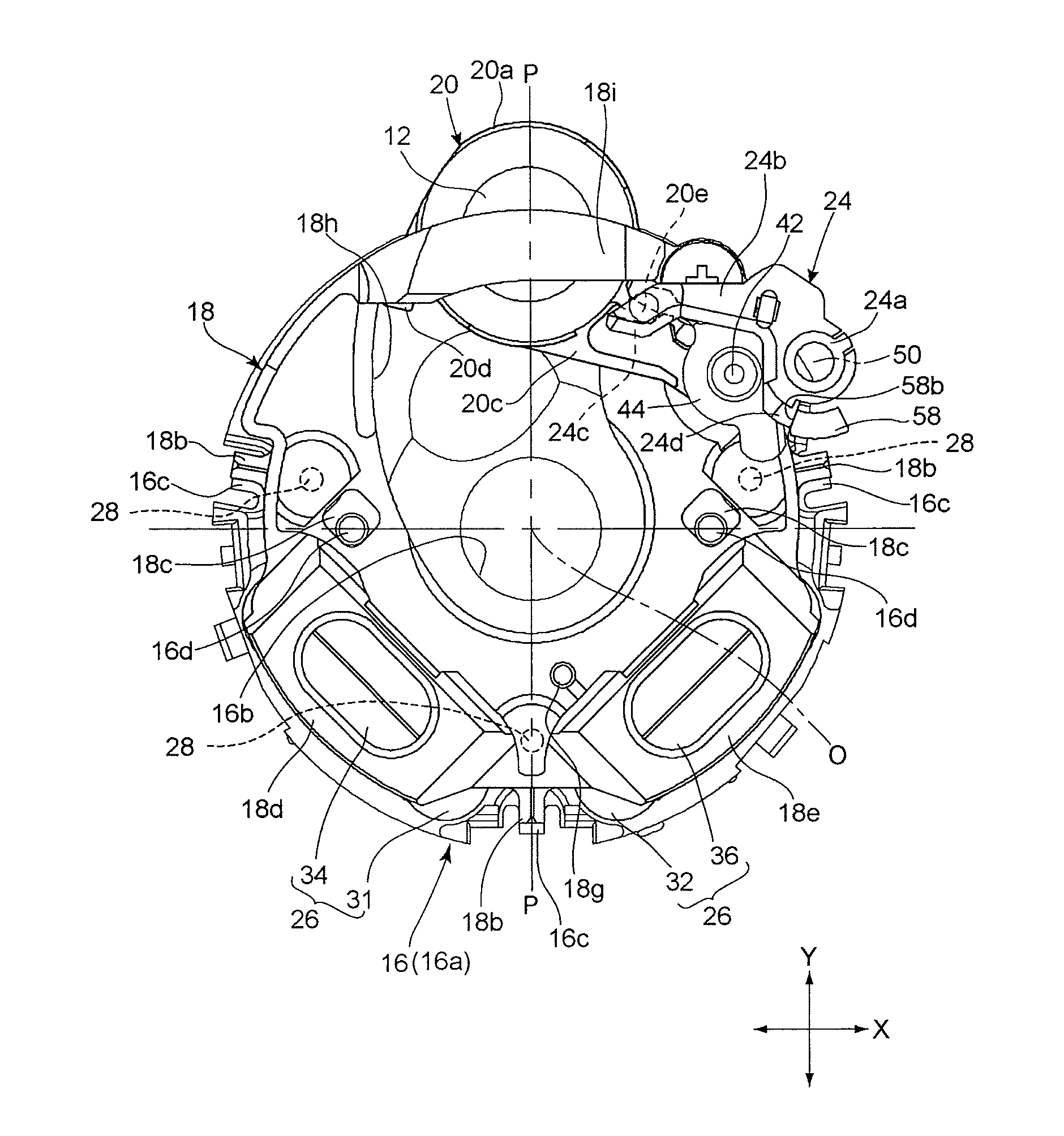
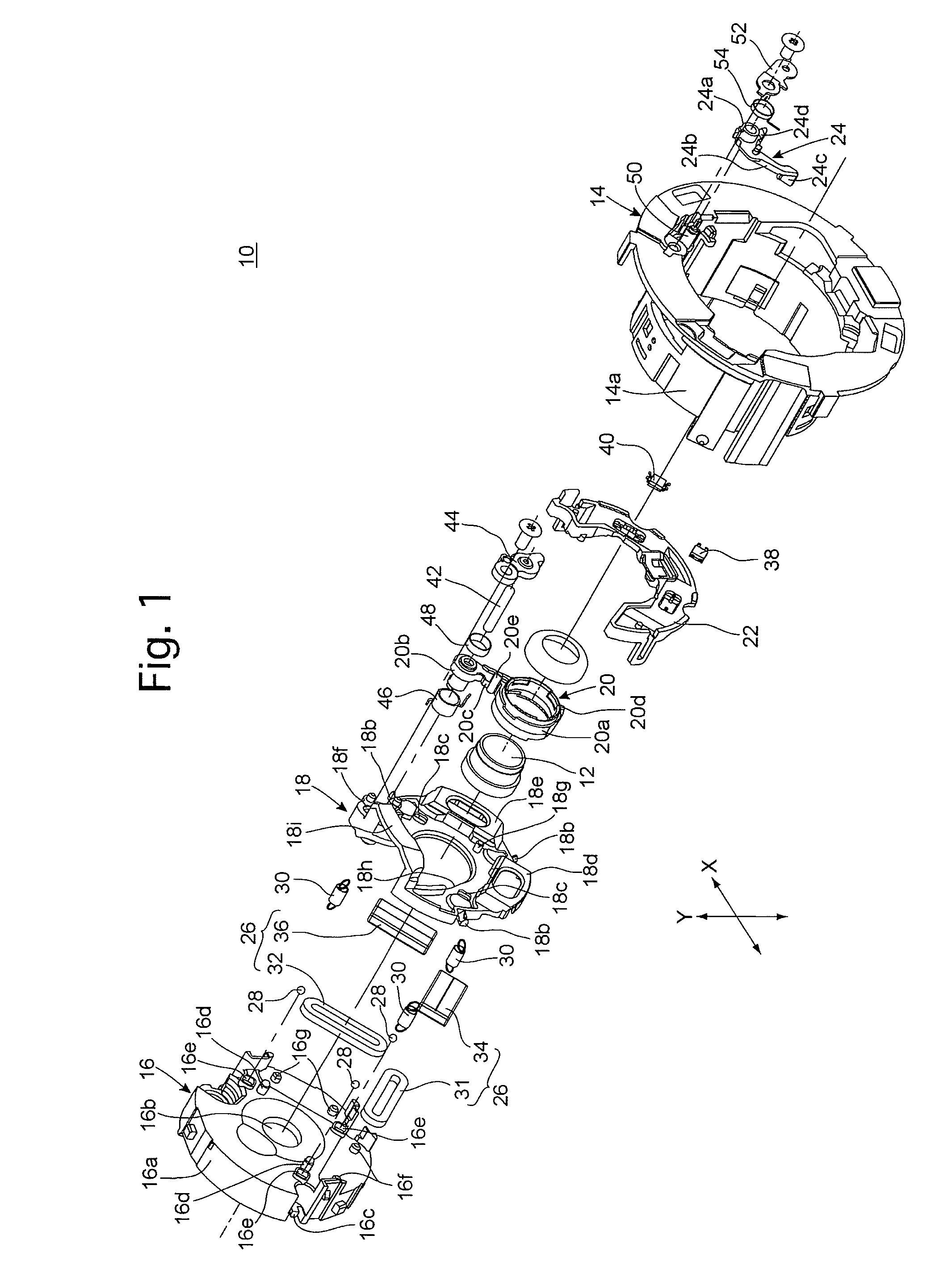
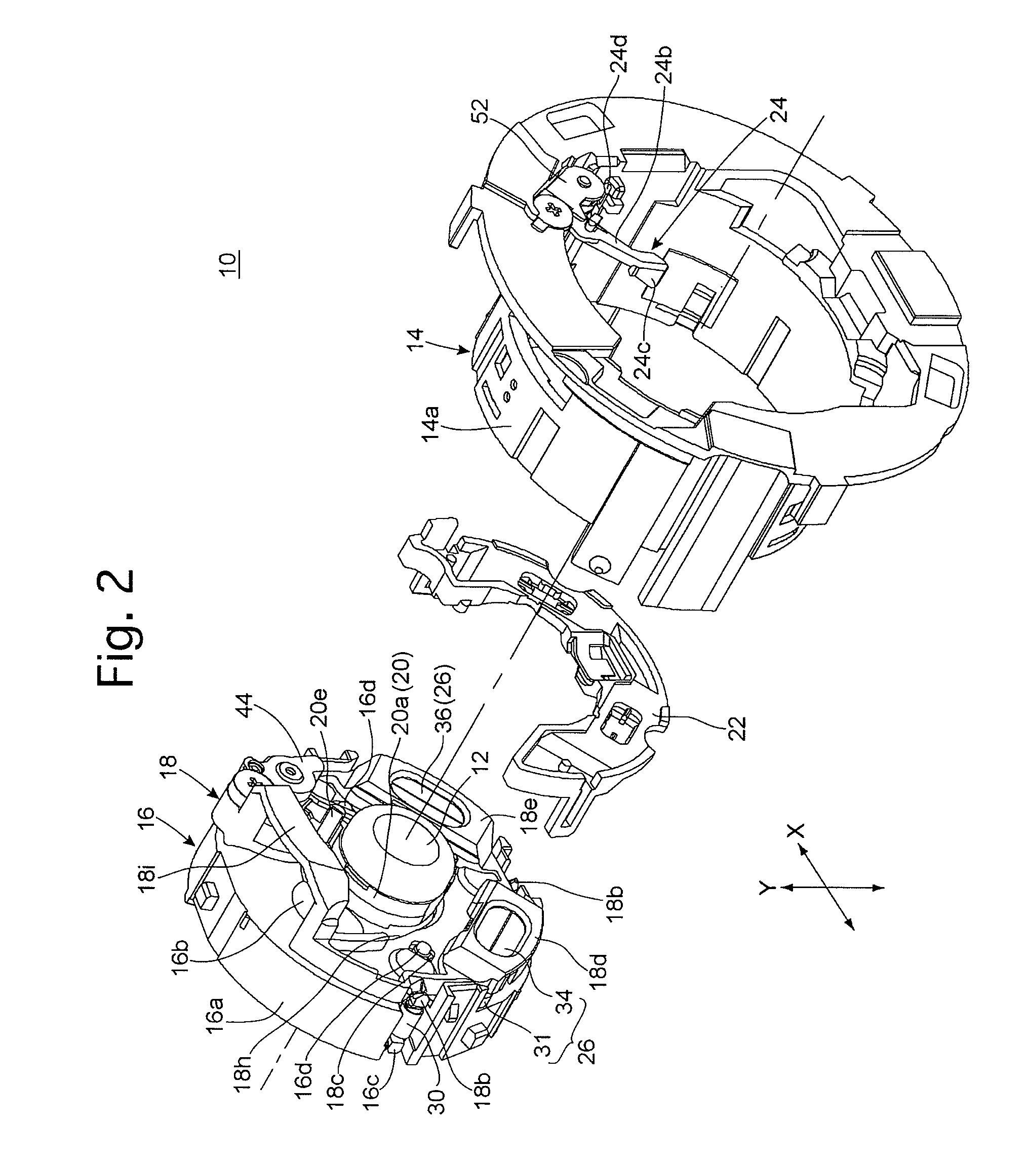
[0028]An anti-shake lens unit 10 shown in FIGS. 1 through 3 supports an insertable / removable image-stabilizing lens (insertable / removable image-stabilizing optical element) 12 which constitutes a part of a photographing optical system of a lens barrel of a camera. As shown in FIG. 1, the anti-shake lens unit 10 is provided with a linear moving ring (advancing / retracting member) 14, and is provided in the linear moving ring 14 with a shutter unit (advancing / retracting member) 16, an anti-shake frame 18, an insertable / removable frame 20, a sensor holder 22, a removal drive lever (removal drive mechanism / rotational relay member) 24 and a pair of anti-shake drive actuators (anti-shake drive mechanism) 26.

[0029]Although the overall structure of the lens barrel in which the anti-shake lens unit 10 is incorporated is not shown in the drawings, the linear moving ring 14 is supported inside the lens barrel thereby in a manner to be linearly movable in a direction along a photographing optica...


PUM


Abstract

A lens barrel having an insertable / removable optical element includes an advancing / retracting member, an anti-shake frame supported by the advancing / retracting member, an insertable / removable frame holding the insertable / removable optical element and supported by the anti-shake frame, an anti-shake drive mechanism, and a removal drive mechanism which moves the insertable / removable frame between the insertion and the removed positions. The anti-shake drive mechanism includes first and second anti-shake drive actuators positioned on the opposite side of the insertion position from the removed position and are respectively positioned on opposite sides of a straight line connecting a center of the insertable / removable optical element at the insertion position and at the removed position. Directions of driving forces produced by the first and second anti-shake drive actuators are at right angles to each other.

Description

BACKGROUND OF THE INVENTION[0001]1. Field of the Invention[0002]The present invention relates to a lens barrel having an image-stabilizing insertable / removable optical element which can be moved to correct image shake and removed to a position outside an anti-shake driving range of the optical element.[0003]2. Description of the Related Art[0004]There has been an increasing number of optical devices such as cameras which are equipped with an anti-shake mechanism (image-stabilizing mechanism / shake reduction mechanism / image stabilizing mechanism) that moves a specific optical element such as a lens element or an image sensor (image pickup device) in a plane orthogonal to an optical axis of an optical system to reduce (correct) image shake. In Japanese Unexamined Patent Publication No. 2007-101993, a technique for removing (radially retracting) an image-stabilizing optical element to a position outside an anti-shake driving range (to a position off an optical axis of the optical system...

Claims


Application Information

Patent Timeline
Patent Type & Authority Patents(United States)
IPC IPC(8): G02B27/64G02B7/02G03B5/06G03B17/00G03B17/04H04N5/228H04N5/232
CPCG02B27/646G03B5/00G03B5/06G03B17/04G03B2205/0015G03B2205/0069G03B2205/0092H04N5/23287G03B2205/00G02B7/04H04N23/687
Inventor SUZUKA, SHINYA
Owner HOYA CORP
Why Eureka
Try Eureka