Confocal optical scanner

A confocal and scanner technology, applied in the field of biomedical microscopic imaging, can solve problems such as difficulty in stabilization, and achieve the effect of improving imaging stability and avoiding the problem of focal plane drift.

Pending Publication Date: 2017-08-11
BEIJING CENTURY SUNNY TECH
View PDF0 Cites 7 Cited by
  • Summary
  • Abstract
  • Description
  • Claims
  • Application Information

AI Technical Summary

Problems solved by technology

However, the current confocal imaging systems can only achieve three-dimensional scanning imaging of the sample by changing the position of the microscope objective lens in the vertical direction, or changing the position of the sample.
Both of these two focusing mechanisms cannot avoid the drift of the focal plane, and it is difficult to image the sample on the same focal plane stably and for a long time

Method used


Image

  • Confocal optical scanner
  • Confocal optical scanner
  • Confocal optical scanner

Examples


Embodiment 1

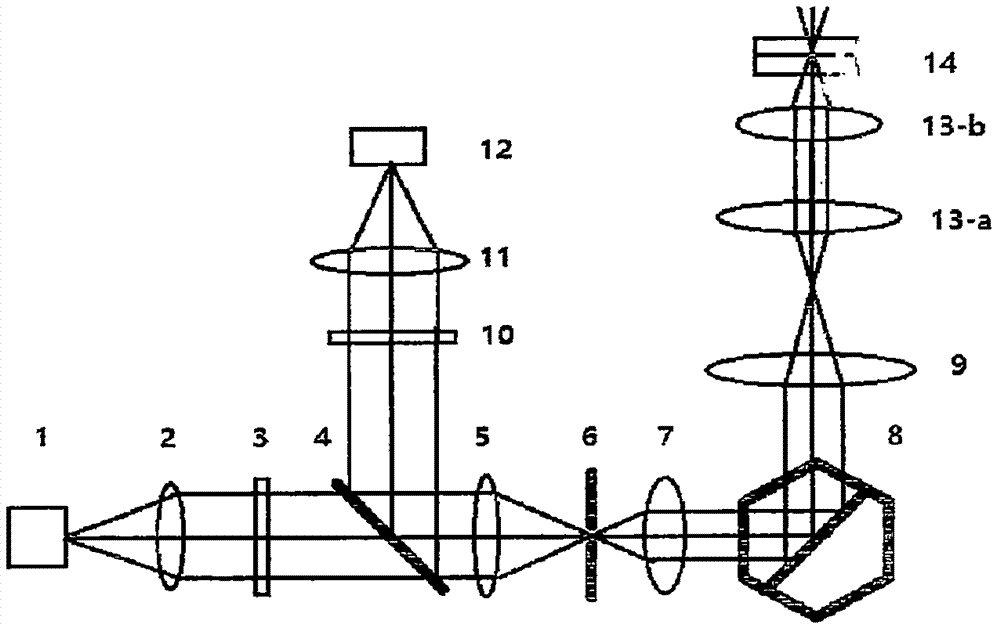
[0030] Fig. 1 is the schematic diagram of the first kind of confocal optical scanner relevant to the present invention, and the mode of operation is as follows:

[0031] Such as Figure 1-a As shown, the computer 17 controls the dynamic focusing lens 7 to turn on the light source 1 at a designated position, and the light emitted by the light source 1 is collimated into collimated light by the collimator mirror 2, and then passes through the excitation filter 3 to select a suitable wavelength band to obtain the excitation light; The excitation light passes through the dichroic beam splitter 4, converges through the converging lens 5 and passes through the pinhole 6, and then passes through the dynamic focusing lens 7, XY scanning galvanometer 8, telecentric scanning lens 9, sleeve lens 3a and objective lens 13b to excite the sample 14; the original path of fluorescence emitted by the sample 14 returns to the dichroic beam splitter 4, then reflects and passes through the emissio...

Embodiment 2

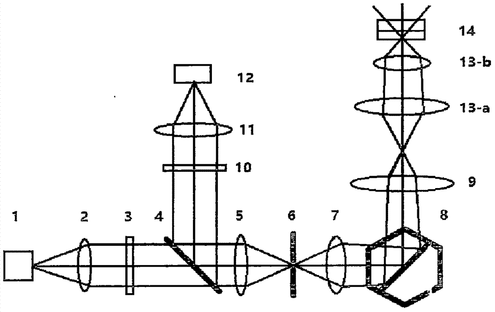
[0037] figure 2 It is a schematic diagram of the second confocal optical scanner related to the present invention. The difference between it and Embodiment 1 is as follows: the pinhole 6 moves back and forth along the optical axis, and the position of the dynamic focus lens 7 is fixed, so that through The illumination light of the pinhole 6 is converted into excitation light in any form of converging, collimating or diverging, so as to realize scanning imaging at different focal planes.

Embodiment 3

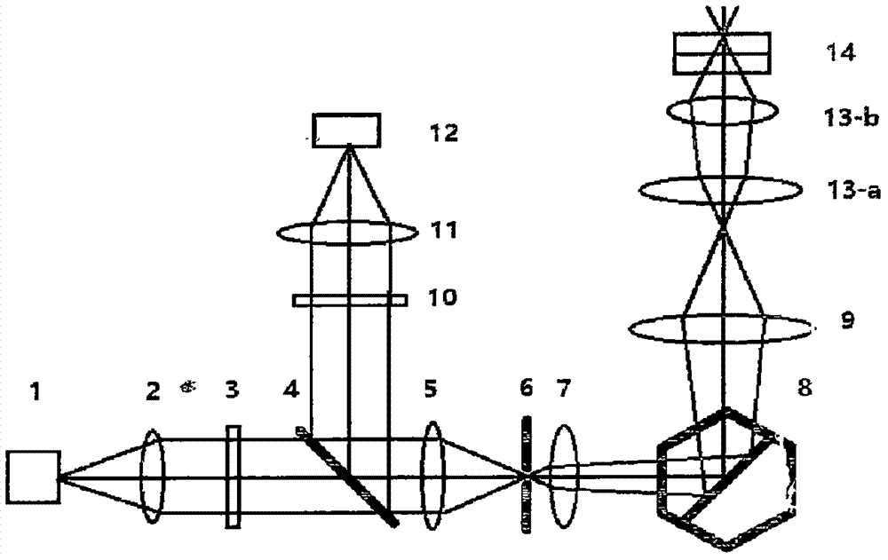
[0039] image 3 It is a schematic diagram of the third confocal optical scanner related to the present invention, and its difference with Embodiment 1 is as follows: through a total reflection mirror 15 and a beam combining mirror 16, two groups of the same, with light source 1, collimator Optical path of straight mirror 2, excitation filter 3, dichroic beam splitter 4, converging lens 5, pinhole 6, dynamic focusing lens 7, XY scanning galvanometer 8, emission filter 10, imaging lens 11 and detector 12 The optical paths of the structures coincide, and then are simultaneously introduced into the microscope (including the tube lens 13a and the objective lens 13b) through the telecentric scanning galvanometer 9, and simultaneously scan samples 14 of different or the same focal plane under different or the same field of view.


PUM


Abstract

A confocal optical scanner that is mainly used in the field of biomedical microscopic imaging, material research and integrated circuit chip detection imaging. A dynamic focusing lens between the mirrors changes the divergence angle of the beam that passes through the pinhole and is reflected by the XY galvanometer, so as to realize the three-dimensional scanning imaging of the sample and obtain a three-dimensional confocal image.

Description

technical field [0001] The invention relates to a confocal optical scanner, in particular to a confocal imaging system for three-dimensional scanning imaging of samples. The invention is mainly used in the field of biomedical microscopic imaging, and can also be used in material research and integrated circuit chip detection imaging. Background technique [0002] With the deepening of cell biology research, the application of fluorescence microscopy imaging is becoming more and more common, and confocal microscopy imaging has received more and more attention. However, the current confocal imaging systems can only achieve three-dimensional scanning imaging of the sample by changing the position of the microscope objective lens in the vertical direction, or changing the position of the sample. Both of these two focusing mechanisms cannot avoid the drift of the focal plane, and it is difficult to image the sample on the same focal plane stably and for a long time. Contents o...

Claims


Application Information

Patent Timeline
Patent Type & Authority Applications(China)
IPC IPC(8): G01N21/64
CPCG01N21/6456
Inventor 赖博王继光
Owner BEIJING CENTURY SUNNY TECH
Why Eureka
Try Eureka