Apparatus and method for fast volumetric fluorescence microscopy using temporally multiplexed light sheets

A light sheet and microscopic equipment technology, applied in microscopes, measuring devices, optics, etc., can solve problems such as low volume frame rate and image quality deterioration, and achieve fast volume frame rate, reduce light damage, and long-term imaging stability Effect

Active Publication Date: 2021-06-08
THE UNIVERSITY OF HONG KONG
View PDF7 Cites 5 Cited by
  • Summary
  • Abstract
  • Description
  • Claims
  • Application Information

AI Technical Summary

Problems solved by technology

This technique produces a temporally shared one-dimensional (1D) point spread function and avoids continuous illumination of the sample, but requires higher laser power to generate the same level of fluorescence counts
Also, the sample stage needs to be scanned to capture the volume frame, so the volume frame rate is low
As a result, inherent stage drift will cause image quality degradation

Method used


Image

  • Apparatus and method for fast volumetric fluorescence microscopy using temporally multiplexed light sheets
  • Apparatus and method for fast volumetric fluorescence microscopy using temporally multiplexed light sheets
  • Apparatus and method for fast volumetric fluorescence microscopy using temporally multiplexed light sheets

Examples


example 1

[0094] Fast volumetric imaging devices can capture continuous video of dynamic processes occurring in biological samples. To demonstrate this, set the diameter to 1 The fluorescent polymer beads are fed into the water and injected into a square glass pipette via a syringe pump. The illumination and detection objectives are positioned orthogonally to the adjacent sides of the glass pipette. This configuration allows the detection objective to capture the dynamic motion of the fluorescent polymer beads in the microfluidic flow. Figure 7 (a) shows a volumetric image of fluorescent polymer beads at 80 ms. Figure 7 (b) shows a volumetric image of fluorescent polymer beads at 680 ms. Figure 7 (c) shows a volumetric image of fluorescent polymer beads at 1.36 s. Figure 7 (d) shows the volume image of fluorescent polymer beads at 1.92 s. The volume frame rate is -25 volumes / second, and the video is used to estimate flow at a rate of 27 / Second.

example 2

[0096] The Rapid Volume Imaging Facility was used to image the vasculature in the mouse intestine and glomeruli in the mouse kidney. Intestinal and kidney tissues were cleared in OPTIClear solution for better optical clarity and stained with DiI (DiIC 18 ) dyes to label endothelial cell membranes. Figure 8 (a) is a volumetric image of the intestinal vascular network structure. This image demonstrates that even angiogenic sprouts can be clearly visualized. Figure 8 (b) shows three glomeruli attached to the vascular network in optically clear mouse kidney tissue. The volume frame rate is 1.6 volumes / second.

example 3

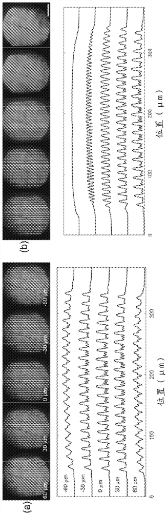
[0098] A fast volumetric imaging device may be configured to incorporate an extended depth of focus (DOF) with wavefront coding (WFC). A predefined phase mask can be placed in the detection path such that it designs the point spread function (psf) of the system to a small depth variation. During deconvolution, a cubic phase mask (CPM) based WFC scheme can be used to achieve extended DOF in fast volumetric imaging devices. The CPM phase function can be described as in u with v is the spatial frequency coordinate, and r is a free optimization parameter. The CPM is placed at the back focal plane of the detection objective (20×, NA=0.4). PSF across depth >50 Almost unchanged. with no CPM (only ~5 This shows a clear extended DOF effect compared to the PSF of DOF). CPM only modulates the phase, and therefore introduces no losses. A psf simulation study shows depth invariance of psf when CPM is added (greater than 50 ) (for example, see Figure 4). The psf images creat...


PUM

PropertyMeasurementUnit
diameteraaaaaaaaaa
diameteraaaaaaaaaa

Abstract

A microscopy device comprises a continuous or pulsed wave laser light source; a pair of parallel mirrors configured to receive light from the light source and reflect an array of incoherent light sheets; a beam encoder (e.g., frequency modulation reticle, Hadamard basis, random modulation pattern) to segment the array of incoherent light sheets and encode each light sheet with a respective frequency in reciprocal space; a lens configured to direct the encoded light sheets towards a biological sample; and an image capturing device configured to receive a fluorescence signal from the biological sample.

Description

Background technique [0001] Biological imaging has been used to image physiologically relevant systems for many years. [0002] A great challenge in understanding the vital processes of complex biological systems in three dimensions (3D) lies in the lack of imaging modalities that enable dynamics to be monitored with sufficiently high spatiotemporal resolution and with low levels of photodamage. Established 3D bioimaging techniques, namely confocal and multiphoton microscopy and light-sheet fluorescence microscopy (LSFM), are bioimaging techniques that operate by decoupling illumination and detection optical paths; and use Different illumination techniques are used to optimize the photon collection efficiency of the system. However, these light-based imaging systems may cause photodamage in biological samples and induce phototoxicity. These light-based imaging systems primarily rely on laser scanning, which often compromises imaging speed because the entire 3D field of view ...

Claims


Application Information

Patent Timeline
Patent Type & Authority Applications(China)
IPC IPC(8): G02B21/00
CPCG02B21/0032G02B21/367G02B21/16G02B21/002G01N21/6458G01N21/6486G01N21/8851G02B21/0076
Inventor 谢坚文任煜轩吴江来刘金成黎芷君
Owner THE UNIVERSITY OF HONG KONG
Why Eureka
Try Eureka