Optical image stabilizer and optical apparatus

a technology which is applied in the field of optical image stabilizer and optical apparatus, can solve the problems of increasing the size of the actuator and the difficulty of holding the correction lens at the neutral position only by the springs, and the increase of the battery consumption amount, so as to reduce the driving stroke of the correction lens, the effect of light weight and larger shak

Inactive Publication Date: 2011-07-19
CANON KK
View PDF20 Cites 8 Cited by
  • Summary
  • Abstract
  • Description
  • Claims
  • Application Information

AI Technical Summary

Benefits of technology

[0010]The present invention provides a compact optical image stabilizer that includes a correction lens having a lighter weight, that can provide an image stabilizing effect to a larger shake while reducing a driving stroke of the correction lens, and that enables reduction of focal shifts and improvement of image stabilization performance. The present invention also provides an optical apparatus including the above described optical image stabilizer.

Problems solved by technology

However, in the spring-hanging-type image stabilizer, the increase of the weight of the correction lens makes it difficult to hold the correction lens at the neutral position only by the springs.
On the other hand, when a spring constant of the springs is increased in accordance with the increased weight of the correction lens, the driving force required to drive the correction lens against the spring force in the image stabilizing operation state is increased, which increases the size of the actuator and a battery consumption amount.
Further, even when the correction lens has a small weight, increasing the driving stroke of the correction lens for the purpose of obtaining an image stabilizing effect for a certain degree of large shake increases power supplied to the actuator, which increases a battery consumption amount.
However, in the image stabilizer disclosed in Japanese Patent Laid-Open No. 2-162320, a long link mechanism for balancing the correction lenses having the opposite optical powers extends in the optical axis direction, which increases the size of the image stabilizer.
This image stabilizer uses a motor and a feed screw to drive the correction lens, which makes it difficult to achieve high-speed driving and good positional accuracy of the correction lens.
In addition, this image stabilizer drives separate correction lenses in the pitch direction and the yaw direction, so that it is difficult to reduce the size.

Method used


Image

  • Optical image stabilizer and optical apparatus
  • Optical image stabilizer and optical apparatus
  • Optical image stabilizer and optical apparatus

Examples


embodiment 1

[0034]First, FIG. 18 shows an external view of a digital camera as an optical apparatus (image-pickup apparatus) including an optical image stabilizer that is a first embodiment (Embodiment 1) of the present invention. Although this embodiment will describe the digital camera integrated with a lens, the optical image stabilizer of this embodiment (and Embodiments 3 to 6 which will be described later) also can be provided in other image-pickup apparatuses such as an interchangeable lens and a video camera.

[0035]Reference numeral 43 denotes a camera body and reference numeral 43a denotes a release button to start an image-pickup operation. Reference numeral 43b denotes a mode dial to set an image-pickup mode. The mode dial 43b has a main switch 43d at the center thereof. Reference numeral 43c denotes a retractable flash. Reference numeral 48 denotes a lens barrel provided at the front part of the camera body 43. The lens tube 48 includes therein an image-pickup optical system. The ima...

embodiment 2

[0095]Embodiment 1 has described the optical image stabilizer provided in the image-pickup apparatus. However, an optical image stabilizer of the present invention also can be applied to an observation apparatus (optical apparatus) such as binoculars or a telescope. An example of the binoculars including the optical image stabilizer will be described.

[0096]Binoculars are generally constituted by objective lenses, prism optical systems, and ocular lenses. FIGS. 9 to 13 show Binoculars in which the optical image stabilizers having the same configuration and function as those of Embodiment 1 are provided between the objective lenses and the prism optical systems.

[0097]It is noted that components in this embodiment identical to or having the same functions as those in Embodiment 1 are denoted with the same reference numerals as those in Embodiment 1.

[0098]FIG. 9 is a front view showing the optical image stabilizer of this embodiment when viewed from the front side (objective lens side)....

embodiment 3

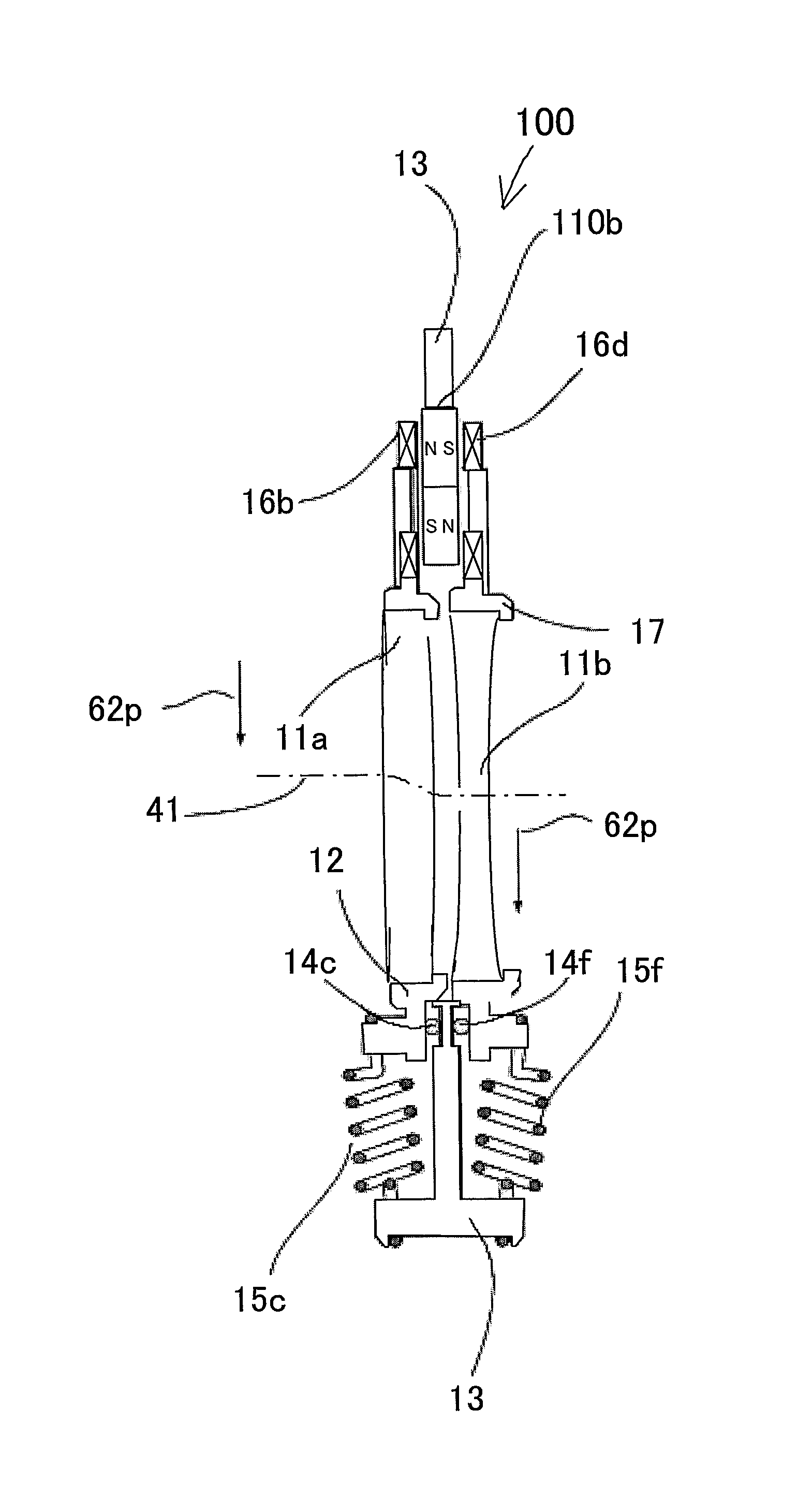
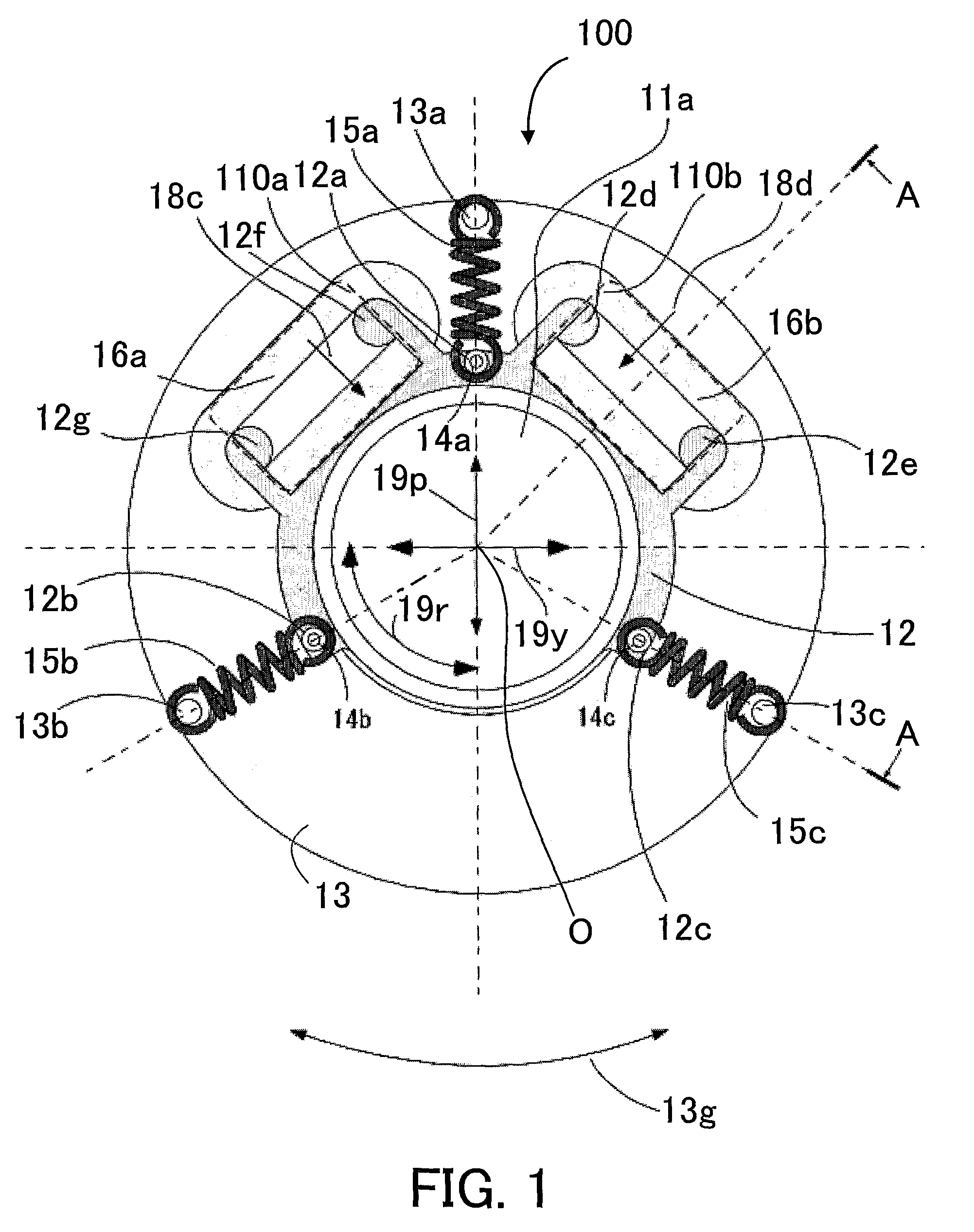
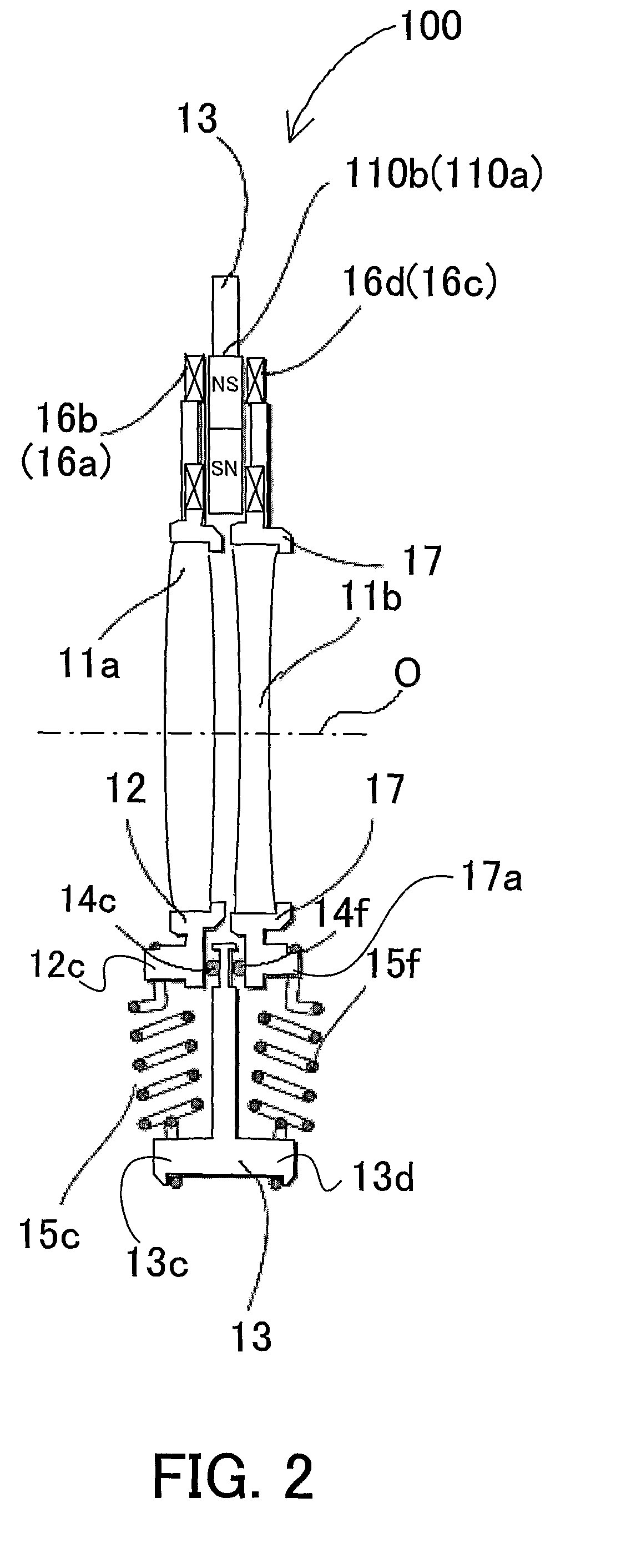
[0133]FIG. 14 is a cross-sectional view showing an optical image stabilizer of a third embodiment (Embodiment 3) of the present invention. This optical image stabilizer is provided in the digital camera described in Embodiment 1. Although the optical image stabilizer of this embodiment basically has the same spring-hanging configuration as that of Embodiment 1, this embodiment is different from Embodiment 1 in the configuration of the actuator. It is noted that components in this embodiment identical to or having the same functions as those in Embodiment 1 are denoted with the same reference numerals as those in Embodiment 1, and their descriptions are omitted.

[0134]In this embodiment, the holding frame 12 holding the positive correction lens 11a is provided with the coils 16a and 16b. The holding frame 17 holding the negative correction lens 11b is provided with the magnets 110a and 110b. Although the coil 16a and the magnet 110a are not shown in the figure, the arrangement of the ...


PUM


Abstract

The optical image stabilizer (100) includes a first movable part including a first lens (11a) having one of positive and negative optical powers, a second movable part including a second lens (11b) having the other of the optical powers, and an actuator driving the first and second movable parts in the directions opposite to each other with respect to a supporting member (13). The actuator includes a first element (110a, 110b) provided on the supporting member, a second element (16a, 16b) provided on the first movable part and facing a first face of the first element, and a third element (16c, 16d) provided on the second movable part and facing a second face formed on an opposite side of the first element from the first face. The first element is one of a magnet and a coil, and the second element and the third element are the other of them.

Description

TECHNICAL FIELD[0001]The present invention relates to an optical image stabilizer that moves a lens in a direction different from an optical axis direction to perform image stabilization, an optical apparatus including the same, and an image-pickup apparatus such as an interchangeable lens and an observation apparatus.BACKGROUND ART[0002]Such an optical apparatus frequently includes, in order to suppress an image shake due to hand jiggling or the like, the optical image stabilizer (hereinafter simply referred to as image stabilizer) that moves a correction lens in a direction different from that of the optical axis (e.g., a pitch direction and a yaw direction which are orthogonal to the optical axis).[0003]Japanese Patent Laid-Open No. 8-184870 discloses an image stabilizer in which a correction lens is supported by springs and is held at a neutral position in a non-image stabilizing operation state, and the correction lens is moved with a driving force generated by an actuator agai...

Claims


Application Information

Patent Timeline
Patent Type & Authority Patents(United States)
IPC IPC(8): G03B17/00
CPCG02B27/646G03B5/00H04N5/23248H04N5/23287G03B2205/0007H04N2101/00G03B2205/0069H04N23/68H04N23/687
Inventor WASHISU, KOICHI
Owner CANON KK
Why Eureka
Try Eureka