
System for identifying regions of interest in visual imagery

Active Publication Date: 2014-07-08
HRL LAB
View PDF10 Cites 49 Cited by
  • Summary
  • Abstract
  • Description
  • Claims
  • Application Information

AI Technical Summary

Benefits of technology

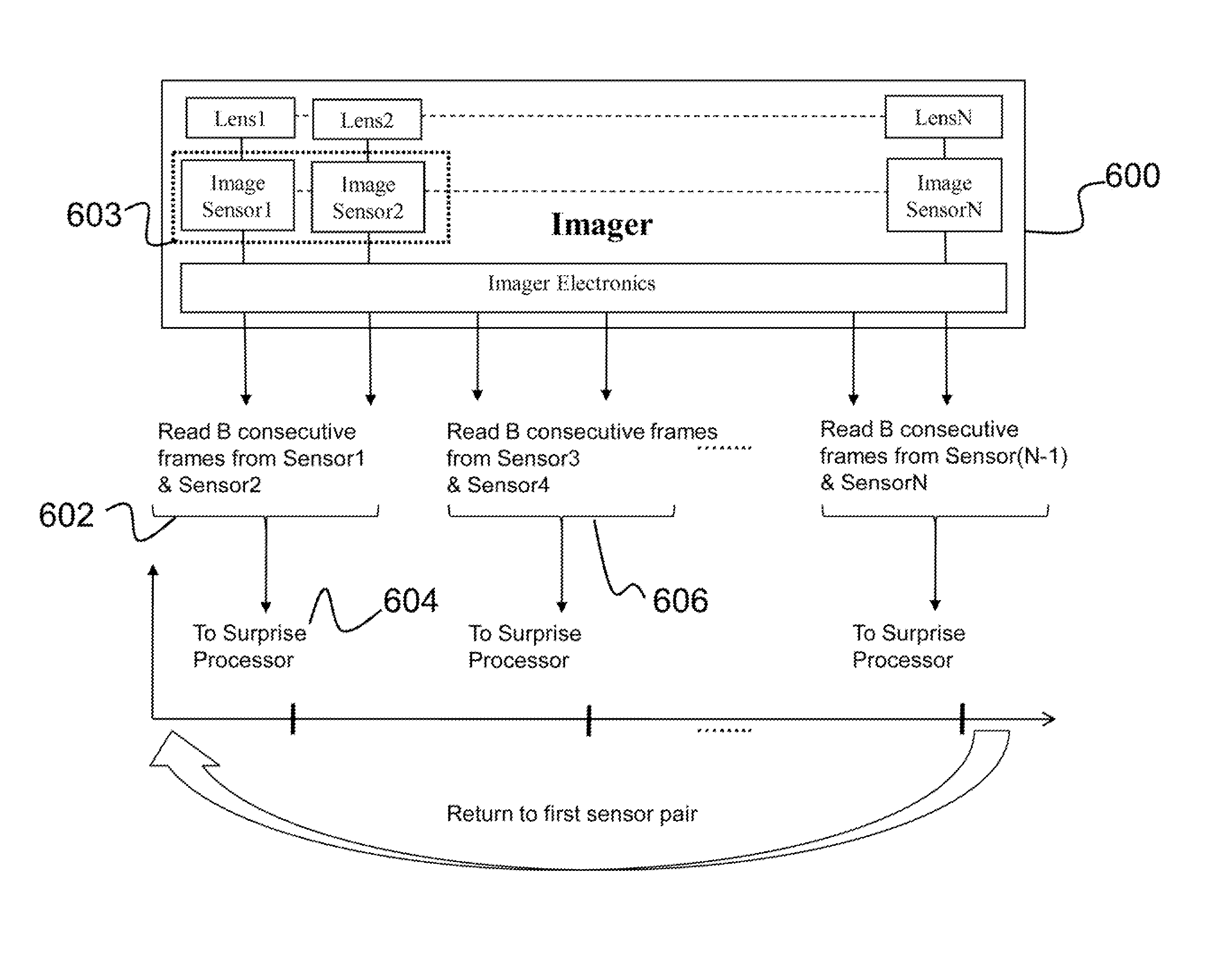
The invention is a technology that uses multiple sensors to effectively surveillance a wide field-of-view (FOV) with a low computational cost. By staggering the activity of sensors across the FOV and using a surprise algorithm, the system can make use of all the factors listed above. Additionally, the system allows users to selectively remove sensors, which in turn adjusts the memory management function to decrease the wait period for remaining sensors.

Problems solved by technology

The concept of surprise is introduced since saliency algorithms may not work well for video of complex natural scenes, as they do not differentiate between continuous saliency and transient saliency.
Also, since surprise must be processed on every pixel in the imagery from the wide FOV, the attention / surprise algorithm requires a large amount of computational resources and often require hardware (e.g., FPGA or ASIC) to run the algorithms.
Depending on the hardware used to run the algorithm, the requirement may either exceed the available resources of the hardware or require larger and more complex hardware (e.g., multiple FPGAs) resulting in bulky and high-power systems.

Method used


Image

  • System for identifying regions of interest in visual imagery
  • System for identifying regions of interest in visual imagery
  • System for identifying regions of interest in visual imagery

Examples


Embodiment Construction

[0050]The present invention relates to a visual surveillance system, and more particularly, to a system for efficiently identifying regions of interest in visual imagery. The following description is presented to enable one of ordinary skill in the art to make and use the invention and to incorporate it in the context of particular applications. Various modifications, as well as a variety of uses in different applications will be readily apparent to those skilled in the art, and the general principles defined herein may be applied to a wide range of embodiments. Thus, the present invention is not intended to be limited to the embodiments presented, but is to be accorded the widest scope consistent with the principles and novel features disclosed herein.

[0051]In the following detailed description, numerous specific details are set forth in order to provide a more thorough understanding of the present invention. However, it will be apparent to one skilled in the art that the present i...


PUM


Abstract

The present invention relates to a system for identifying regions of interest in visual imagery. The system is configured to receive a series of consecutive frames representing a scene as captured from N sensors. The frames include at least a current frame and a previous frame. A surprise map can be generated based on features found in the current frame and the previous frame. The surprise map having a plurality of values corresponding to spatial locations within the scene. Based on the values, a surprise in the scene can be identified if a value in the surprise map exceeds a predetermined threshold.

Description

PRIORITY CLAIM[0001]This is a Continuation-in-Part application of U.S. application Ser. No. 12 / 214,259, entitled, “Visual Attention and Segmentation System,” filed on Jun. 16, 2008, and which is a non-provisional application of U.S. Provisional Application No. 60 / 944,042, entitled, “A Bio-Inspired System for Visual Object-Based Attention and Segmentation,” filed on Jun. 14, 2007.STATEMENT REGARDING FEDERALLY SPONSORED RESEARCH OR DEVELOPMENT[0002]This invention was made with Government support under Contract No. W31P4Q-08-C-0254. The Government has certain rights in the invention.FIELD OF INVENTION[0003]The present invention relates to a visual surveillance system, and more particularly, to a system for efficiently identifying regions of interest in visual imagery.BACKGROUND OF INVENTION[0004]Recently, a great deal of interest has been generated in automated surveillance systems that utilize a wide field-of-view (FOV) to detect anomalies in a panoramic view or scene. Such systems ty...

Claims


Application Information

Patent Timeline
IPC IPC(8): G06K9/00
CPCG06K9/4623G06K9/00771G06K9/3241G06V20/52G06V10/96G06V10/451G06V10/806G06F18/253
Inventor KHOSLA, DEEPAKBHATTACHARYYA, RAJANMUNDHENK, TERRELL N.HUBER, DAVID J.
Owner HRL LAB
Learn More