Valve train for an internal combustion engine

A transmission device and internal combustion engine technology, applied in the direction of valve devices, machines/engines, mechanical equipment, etc., can solve the problems of high design costs, high control technology costs, etc., and achieve the effects of low calculation costs, reduced adjustment costs, and reduced design costs

Inactive Publication Date: 2014-06-11
VOLKSWAGEN AG
View PDF7 Cites 5 Cited by
  • Summary
  • Abstract
  • Description
  • Claims
  • Application Information

AI Technical Summary

Problems solved by technology

Disadvantages of this phase regulator are the high design complexity and high control engineering complexity for the independent phase adjustment of the two axes

Method used


Image

  • Valve train for an internal combustion engine

Examples


Embodiment Construction

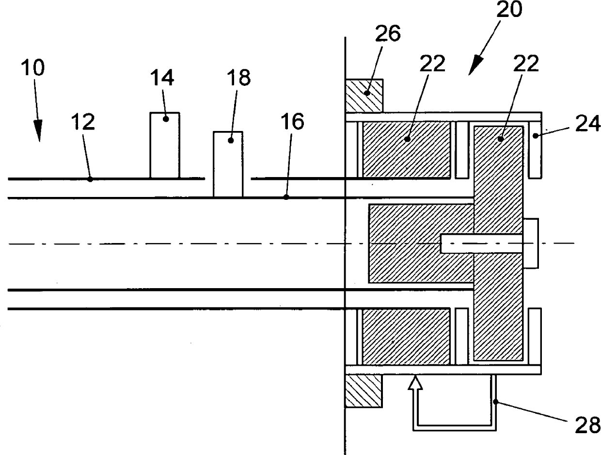
[0025] figure 1 The main components of the valve train according to the invention are shown in a schematic diagram. It includes a camshaft 10 which is designed as a double, hybrid camshaft. To this end, the camshaft includes an outer shaft 12 with a plurality of cams 14 distributed over its length, which are provided for actuating exhaust valves of an internal combustion engine. An inner shaft 16 is rotatably mounted within the outer shaft 12 . Also arranged on the outer side of the inner shaft 16 are a plurality of cams 18 distributed over its length, which serve to control the intake valves of the internal combustion engine.

[0026] The camshaft 10 is connected with one end to a phase adjuster 20 . The phase adjuster comprises two actuators, wherein a first actuator is non-rotatably connected to the inner shaft 16 of the camshaft 10 and a second actuator is non-rotatably connected to the outer shaft 12. rotationally connected. The actuator has a rotor 22 with adjusting...


PUM


Abstract

The invention relates to a valve train for an internal combustion engine with at least two cam shafts and a phase regulator (20), wherein the phase regulator (20) comprises a drive wheel (26), a first actuator which is connected to a first of the cam shafts, and a second actuator which is connected to a second of the cam shafts. By adjusting the first and/or the second actuator, a phase angle of the respective cam shaft can be adjusted relative to the drive wheel (26). Said valve train is characterized in that the adjustment of the second actuator is implemented based upon the adjustment of the first actuator.

Description

technical field [0001] The invention relates to a valve train for an internal combustion engine with at least two camshafts and a phase adjuster, wherein the phase adjuster comprises a drive wheel, a first actuator and a second actuator , wherein the first actuator is connected to the first camshaft of the camshafts against relative rotation, and the second actuator is connected to the second camshaft of the camshafts against rotation , wherein, by adjusting the first and / or second actuator, the phase angle with respect to the drive wheel can be adjusted. Background technique [0002] A valve train for a piston internal combustion engine each comprises at least one, usually two, intake and exhaust valves for each cylinder of the internal combustion engine. The intake and exhaust valves are controlled via camshafts, with internal combustion engines having more than two valves usually using two camshafts per cylinder. The arrangement of the camshafts is often such that one c...

Claims


Application Information

Patent Timeline
Patent Type & Authority Applications(China)
IPC IPC(8): F01L1/053F01L1/344
CPCF01L1/34413F01L1/053F01L1/344F01L2001/34489F02D13/0249F02D13/0261
Inventor A.格勒嫩迪伊克M.范德海伊登
Owner VOLKSWAGEN AG
Why Eureka
Try Eureka