
Aircraft energy state display

a technology of energy state display and aircraft, which is applied in the field of display information, can solve the problems of aircraft stall, damage to aircraft flaps or other aircraft systems, and difficulty in stopping the aircraft before the aircra

Active Publication Date: 2014-07-08
THE BOEING CO
View PDF6 Cites 35 Cited by
  • Summary
  • Abstract
  • Description
  • Claims
  • Application Information

AI Technical Summary

Benefits of technology

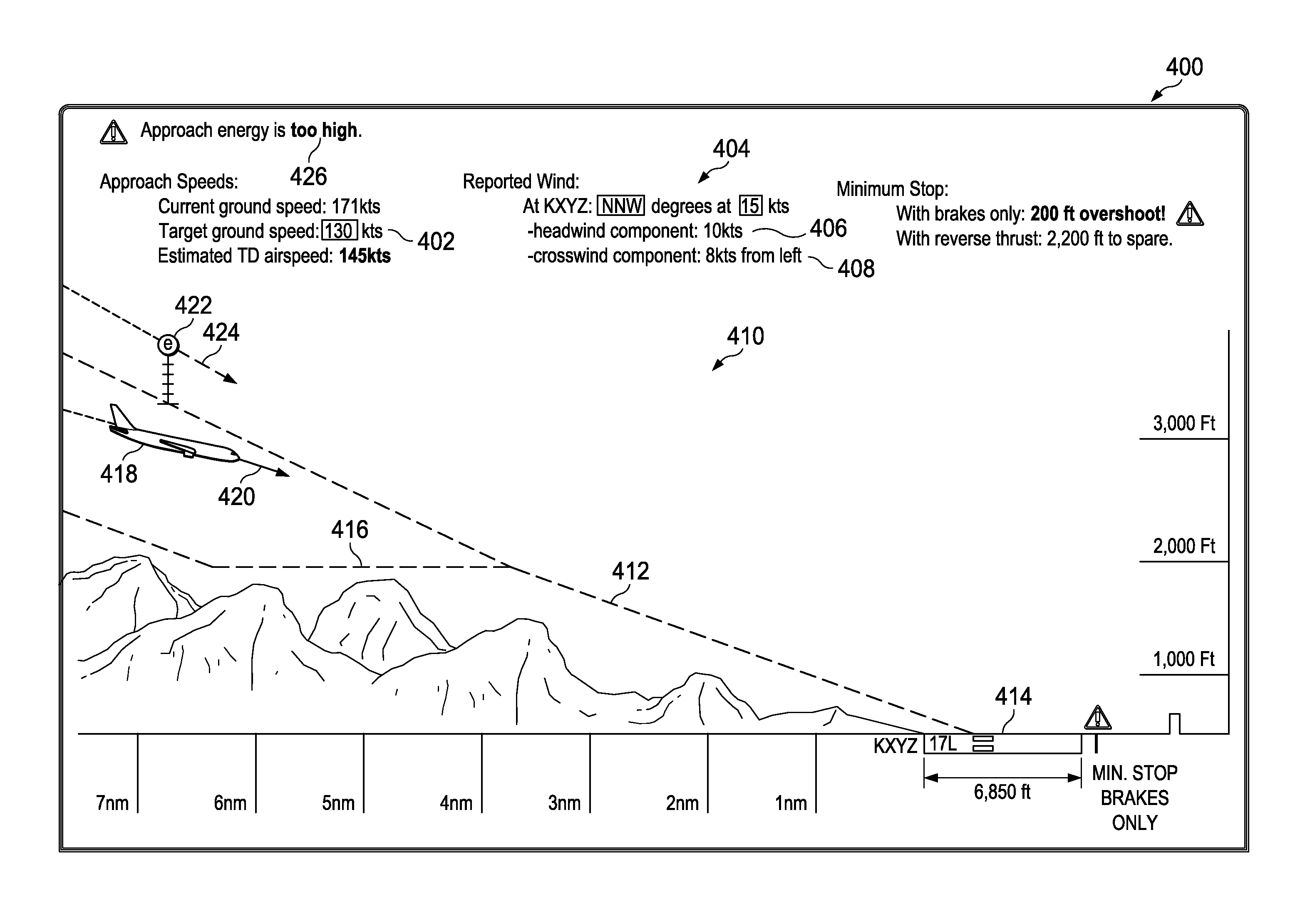
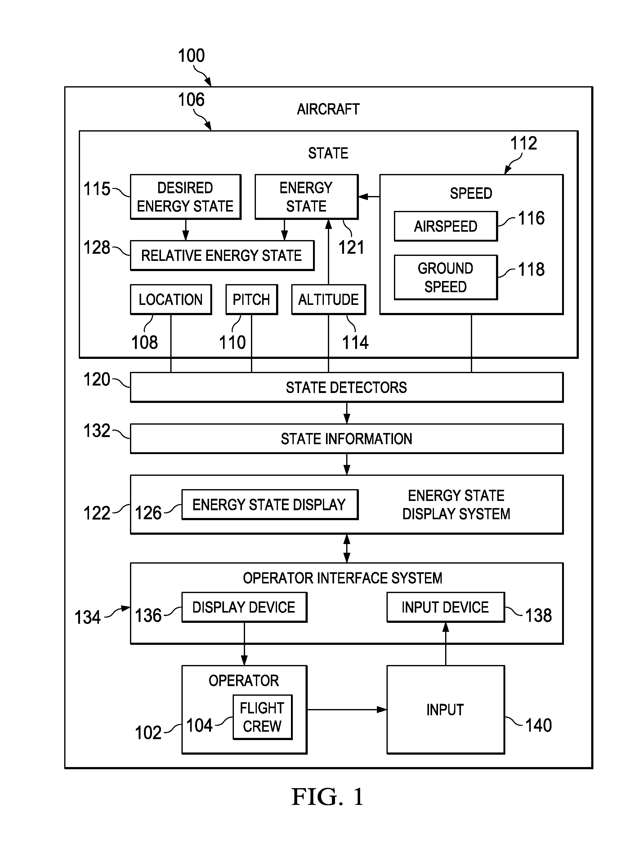
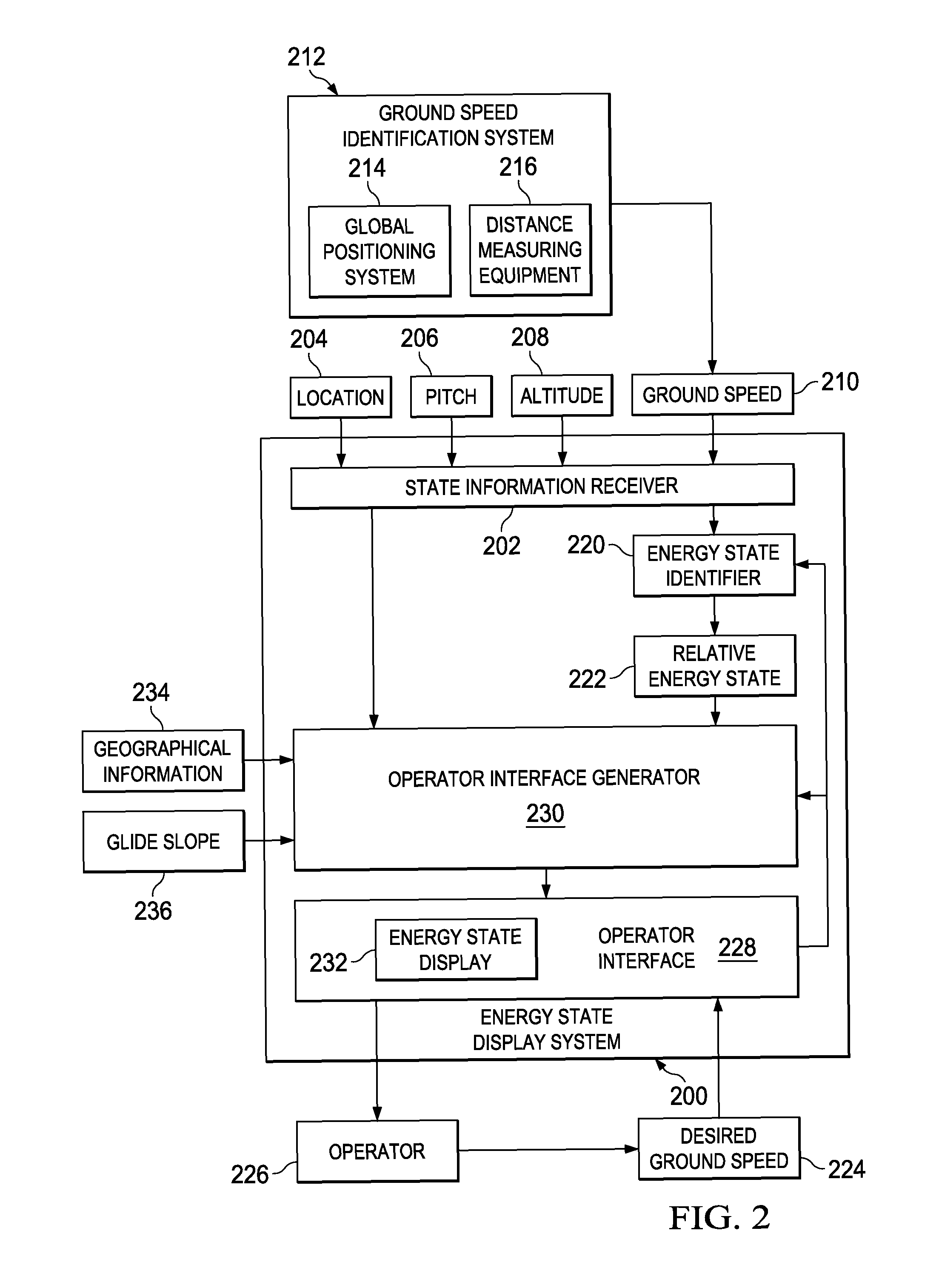
The patent describes a method and apparatus for displaying and identifying the energy state of an aircraft based on its speed and altitude. This information can be used to display the energy state of the aircraft on a screen for the pilot. Additionally, the patent also describes a method for identifying the projected stopping point of the aircraft based on the energy state. The technical effect of these innovations is improved safety and communication for piloted aircraft, allowing for better decision-making and control during approach to landing.

Problems solved by technology

If the airspeed of an aircraft is too low, the aircraft may stall.
An airspeed that is too high during cruise flight of the aircraft may cause flutter.
An airspeed that is too high during an approach to landing may cause damage to the aircraft flaps or other aircraft systems.
If the ground speed of an aircraft is too high during approach and landing, the aircraft may land beyond the end of the runway, or may land at a position on the runway and with such speed that it may be difficult to stop the aircraft before the aircraft reaches the end of the runway.
Currently, ground speed is not usually considered during many aircraft operations.
Controlling an aircraft so that both the airspeed and ground speed of the aircraft are within desired limits may be challenging in some cases under some operational conditions.
For example, a sudden increase in the headwind encountered by an aircraft during an approach and landing operation may cause the airspeed of the aircraft to increase suddenly.
However, reducing the power output of the aircraft engines may reduce the ground speed of the aircraft to a speed that is below the desired ground speed for landing the aircraft.
For example, reducing the power setting in this case may reduce the ground speed below a desired ground speed for responding to wind shears, downbursts, and other sudden changes in the winds around the aircraft, such as when a headwind gust suddenly dies out.

Method used


Image

  • Aircraft energy state display
  • Aircraft energy state display
  • Aircraft energy state display

Examples


Embodiment Construction

[0022]The different illustrative embodiments recognize and take into account a number of different considerations. “A number,” as used herein with reference to items, means one or more items. For example, “a number of different considerations” means one or more different considerations.

[0023]The different illustrative embodiments recognize and take into account that currently, the ground speed of an aircraft may not be taken into account to determine the energy state of an aircraft during an approach to landing. The different illustrative embodiments recognize and take into account that using ground speed information to determine the energy state of an aircraft during approaches may improve the quality and increase the safety of aircraft landing, especially in adverse weather conditions.

[0024]The different illustrative embodiments recognize and take into account that the information provided to pilots on final approach to landing may not allow the pilot to respond in a desired manne...


PUM


Abstract

A method and apparatus for displaying an energy state of an aircraft. The energy state of the aircraft is identified by a processor unit based on a speed of the aircraft and an altitude of the aircraft. An indication of the energy state is displayed by the processor unit.

Description

BACKGROUND INFORMATION[0001]1. Field[0002]The present disclosure relates generally to systems and methods for displaying information for indicating the state of an aircraft to a flight crew. More particularly, the present disclosure relates to displaying information indicating the energy state of an aircraft to a flight crew as the aircraft is descending to land.[0003]2. Background[0004]Airspeed is the speed of an aircraft in flight relative to the air around the aircraft. If the airspeed of an aircraft is too low, the aircraft may stall. An airspeed that is too high during cruise flight of the aircraft may cause flutter. An airspeed that is too high during an approach to landing may cause damage to the aircraft flaps or other aircraft systems.[0005]Ground speed is the speed of an aircraft with respect to the ground over which it is flying. At certain times during the operation of an aircraft, it may be desirable that the ground speed of the aircraft is not too high or too low. For ...

Claims


Application Information

Patent Timeline
IPC IPC(8): G06F17/00G05D1/06
CPCG01C23/00B64D43/02G08G5/0021G08G5/025
Inventor BUSH, LARRY WAYNECLARK, NEIL JOHN
Owner THE BOEING CO
Learn More