End stop for slide fastener

a technology for fasteners and end stops, which is applied in the direction of snap fasteners, slide fasteners, press-button fasteners, etc., can solve the problems of reducing strength, affecting the appearance of the product, so as to achieve the effect of increasing the contact area

Active Publication Date: 2014-07-15
YKK CORP
View PDF12 Cites 6 Cited by
  • Summary
  • Abstract
  • Description
  • Claims
  • Application Information

AI Technical Summary

Benefits of technology

[0018]According to the invention, the end stop for a slide fastener includes the base, the pair of legs, which extends from the base, and the receptacle, which is surrounded by the base and the pair of legs. The pair of legs has the pair of opening-side ends, which is provided opposite to the base, and the pair of protrusions, which is provided in the receptacle adjacent to the opening-side ends, and protrudes inward further than opposing surfaces of the pair of opening-side ends.
[0019]Accordingly, in the state in which the core is positioned in the setting position, the core can increase the contact area with the pair of protrusions, which protrudes further than the opposing surfaces of the opening-side ends, such that the core can be firmly set during crimping. Furthermore, since the pair of protrusions having the foregoing shape can sufficiently maintain the contact area with the core even after the crimping, the top end stop can strongly fix the core even if the size of the top end stop is small.

Problems solved by technology

When crimped, if the setting position is not reliably positioned, the appearance is inferior, and the aspect in which the protrusions are caught and brought by the core changes.
Consequently, there is a probability that the strength decrease.

Method used


Image

  • End stop for slide fastener
  • End stop for slide fastener
  • End stop for slide fastener

Examples


first embodiment

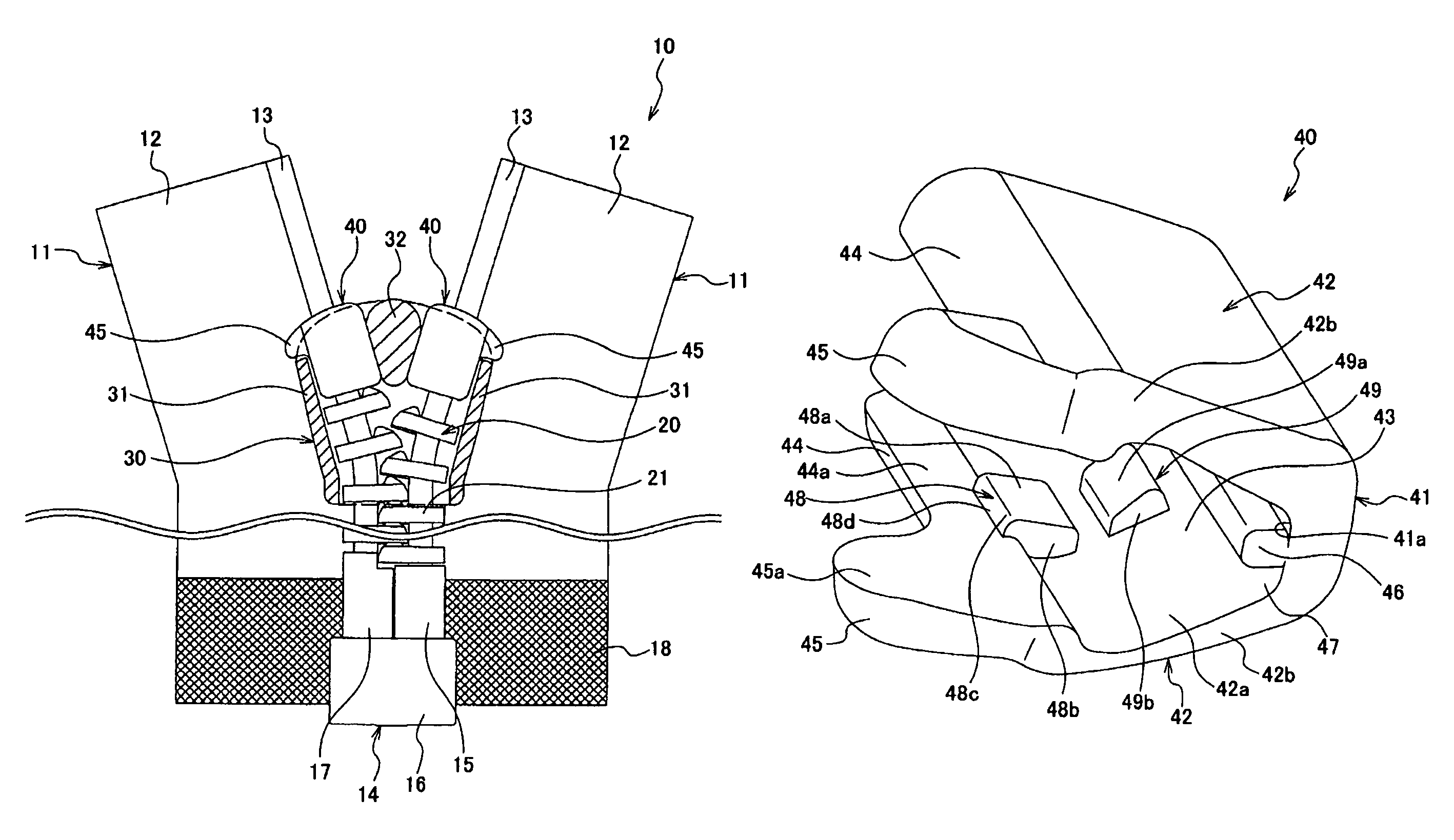
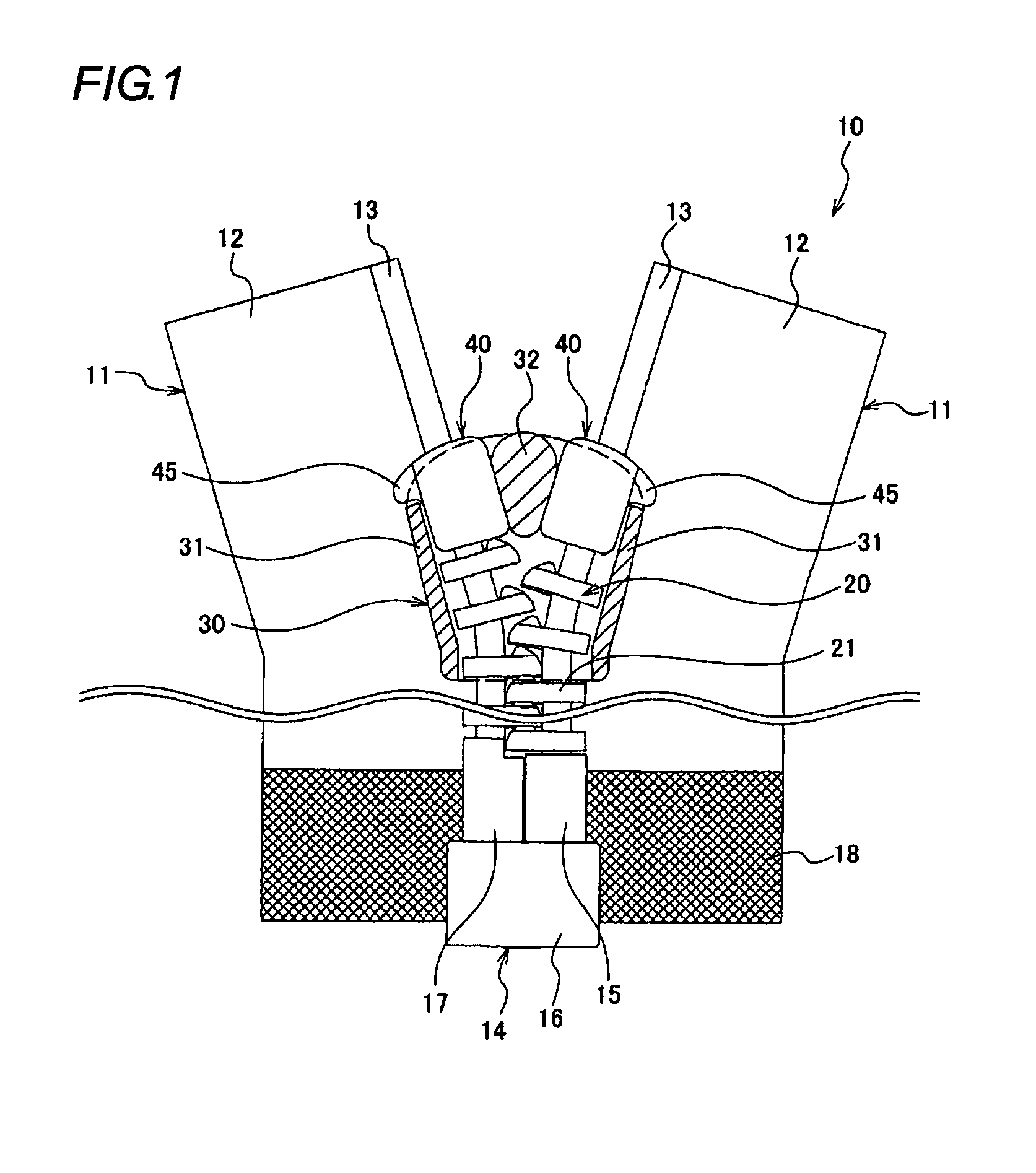
[0032]FIG. 1 shows a slide fastener 10 to which a top end stop as an end stop for a slide fastener according to the invention is applied. The slide fastener 10 includes a pair of left and right fastener tapes 11, a pair of left and right fastener element rows 20, the left fastener element row 20 being provided on the left fastener tape 11, the right fastener element row 20 being provided on the right fastener tape 11, and a slider 30, which causes the left and right fastener element rows 20 to engage with and disengage from each other. In response to the slider 30 being moved forward and backward, the left and right fastener element rows 20 engage with and disengage from each other.

[0033]The pair of left and right fastener tapes 11 includes a pair of tape members 12, which continuously extends in the lengthwise direction and is arranged in parallel in the width direction, and enlarged cores 13, each of which is provided on a corresponding one of opposing tape edges of the respective...

second embodiment

[0053][Second Embodiment]

[0054]FIG. 7 is a front elevation view of a slide fastener to which a bottom end stop 50 as an end stop for a slide fastener according to a second embodiment of the invention is applied, in place of the separable end stop 14 according to the first embodiment. The same reference numerals will be used to designate components equivalent to those of the first embodiment, and descriptions thereof will be omitted or simplified.

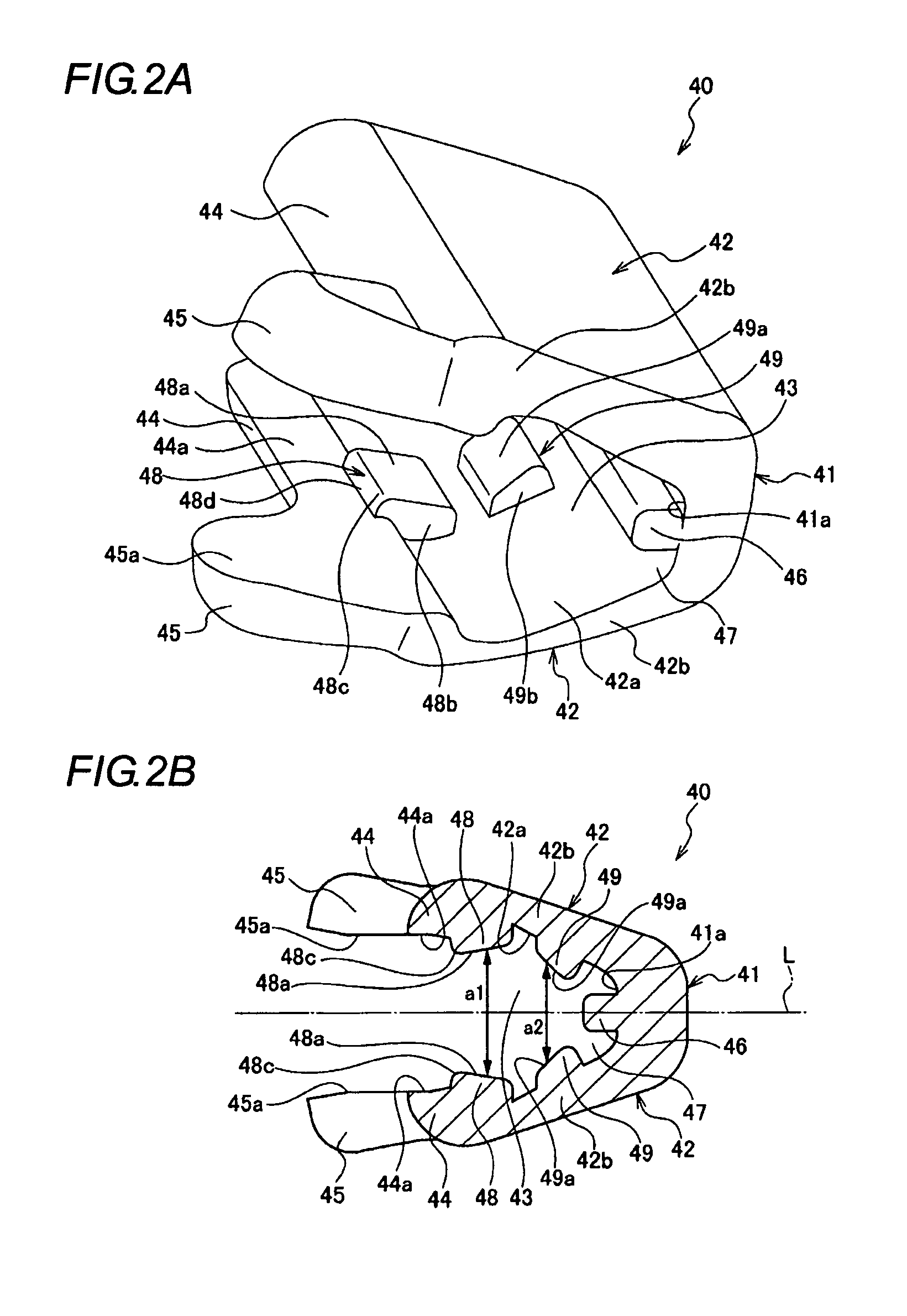
[0055]As shown in FIG. 8 and FIG. 9, the bottom end stop 50 includes a substantially flat base 51, which forms the central portion and has a predetermined length, one pair of legs 52, which extends in the same direction from the surface of the base 51 such that the legs 52 gradually expand from opposite longer edges of the base 51, another pair of legs 52′, which is provided opposite to one pair of legs 52 and extends in the same direction from the surface of the base 51. The cross-section of the bottom end stop 50 is substantially H-shaped....


PUM


Abstract

There is provided an end stop for a slide fastener, in which the attachment strength can be ensured irrespective of the size of the end stop, and a core can be firmly set to a setting position with respect to the end stop. The end stop has a base and a pair of legs which extend from the base, and the end stop is formed with a receptacle which is surrounded by the base and the pair of legs. The pair of legs have a pair of opening-side ends which are provided opposite to the base, and a pair of protrusions which are provided in the receptacle adjacent to the opening-side ends, the pair of protrusions protruding inward further than opposing surfaces of the pair of opening-side ends.

Description

[0001]This application is a national stage application of PCT / JP2009 / 071616 which is incorporated herein by reference.TECHNICAL FIELD[0002]The present invention relates to an end stop for a slide fastener, and more particularly, to an end stop for a slide fastener, which is implemented as a top end stop or a bottom end stop, which is made of metal, the top or bottom end stop being attached to a fastener tape having a core on one edge by being connected to a fastener element, and having the function of stopping the slider that is sliding.BACKGROUND ART[0003]FIG. 10 depicts a top end stop 100 disclosed in Patent Document 1. The top end stop 100 is attached to enlarged cores, each of which is formed on a respective edge of fastener tapes. The top end stop 100 has a pair of legs 102 extending from both ends of a base 101, and is fastened to the core by crimping the pair of legs 102 in the state in which the core is received in a receptacle 103 that is surrounded by the base 101 and the ...

Claims


Application Information

Patent Timeline
Patent Type & Authority Patents(United States)
IPC IPC(8): A44B19/38
CPCY10T24/2593Y10T24/2598A44B19/36Y10T24/2595Y10T24/2596
Inventor KEYAKI, KEIICHIHONDA, SHINYA
Owner YKK CORP
Why Eureka
Try Eureka