Mechanical locking system for floor panels

a technology of locking system and floor panel, which is applied in the direction of floor, building components, covering/lining, etc., can solve the problems of tongue being easily damaged or falling out of the groove, the whole locking system is sensitive, and the tongue is difficult to connect into the groov

Active Publication Date: 2014-07-15
VÄLINGE INNOVATION AB
View PDF389 Cites 131 Cited by
  • Summary
  • Abstract
  • Description
  • Claims
  • Application Information

AI Technical Summary

Benefits of technology

[0017]A basic objective of embodiments of the present invention is to provide an improved mechanical locking system comprising a tongue that locks automatically during folding without any snapping parts that are displaced inwardly and outwardly during locking.
[0018]A first specific objective of embodiments is to create a non-snapping tongue with a simple cross section that could be connected in a horizontally extending fixation groove with limited depth, which surrounds and protects a major part of the tongue.
[0024]The above described locking system and the tongue allows that panels could be locked automatically during vertical folding or vertical displacement without any snapping parts that are active and that create snapping resistance. A strong locking could be obtained with a tongue that has limited flexibility and that is fixed into the fixing groove during production, transport and installation. Only a rather limited horizontal turning of the rocker arms is required to lock the panels vertically.

Problems solved by technology

The main problems with know flexible tongues are that the tongue must be made of materials that are rather flexible, that the snapping creates a resistance during folding and that the major part the tongue must be displaced in a groove during locking.
There are several disadvantages related to such locking systems.
The tongue is difficult to connect into a groove since the whole tongue must turning vertically during locking.
This makes the whole locking system very sensitive to cutting of the panel across the joint and the tongue could easily be damaged or fall out from the groove.
This affects the stability of the edge in a negative way.

Method used


Image

  • Mechanical locking system for floor panels
  • Mechanical locking system for floor panels
  • Mechanical locking system for floor panels

Examples


Embodiment Construction

[0032]To facilitate understanding, several locking systems in the figures are shown schematically. It should be emphasised that improved or different functions can be achieved using combinations of the preferred embodiments.

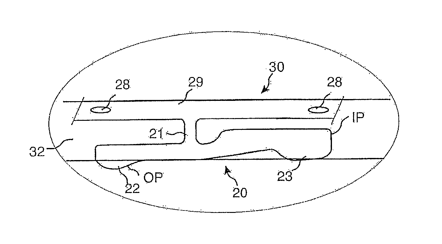
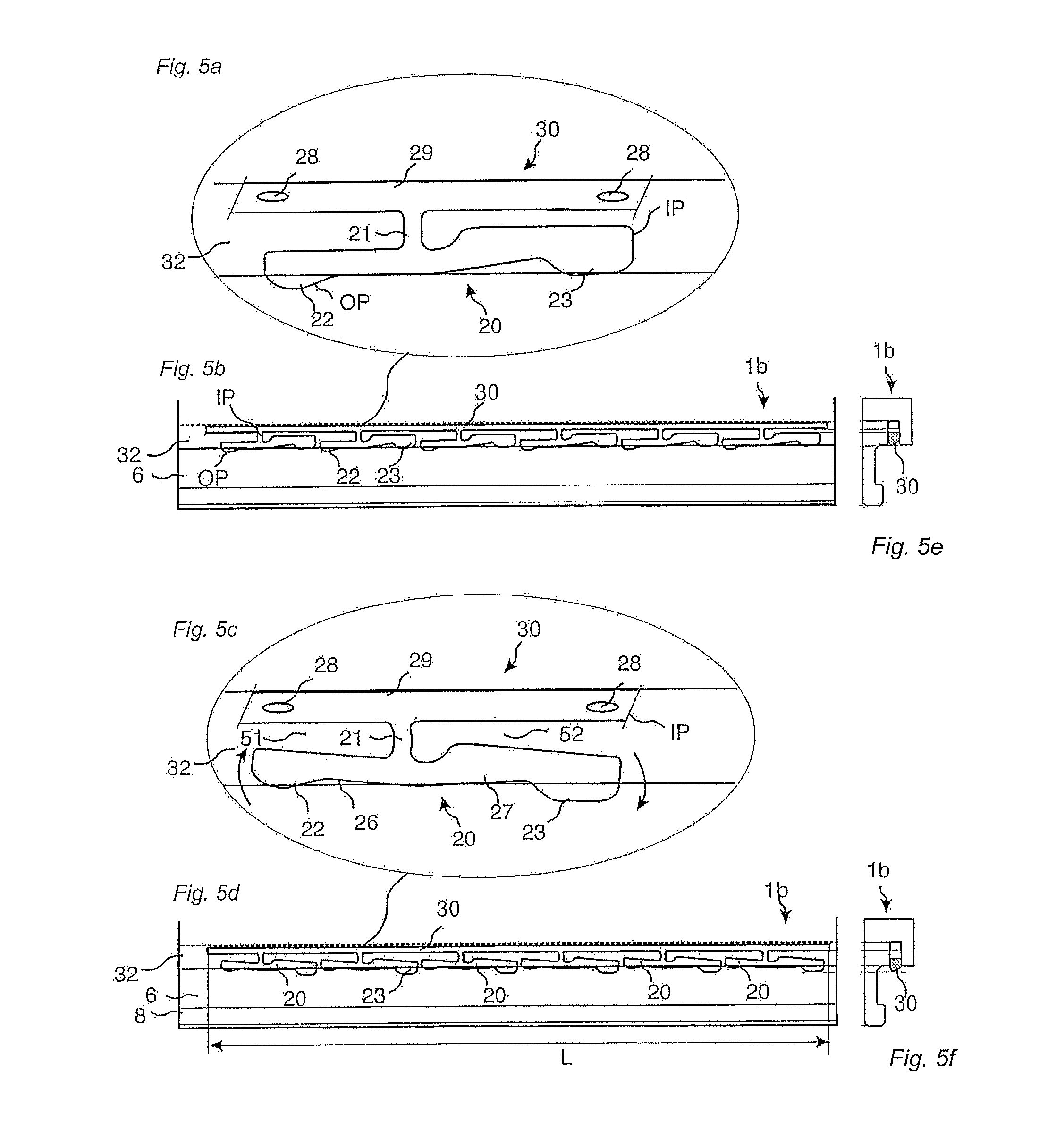
[0033]FIGS. 5a-5f show a tongue 30 according to an embodiment of the invention. FIGS. 5a, 5b and 5e show a tongue 30, which is inserted into a fixation groove 32 of a panel 1b, comprises an inner part IP with a main tongue body 29 and a rocker arm 20 which is connected with a fastening device 21 to the main tongue body 29.

[0034]FIG. 5c shows that the rocker arm comprises a pressing protrusion 22 located on a pressing arm 26 and a locking protrusion 23 located on a locking arm 27. The rocker arm is designed such that the locking protrusion 23 is displaced outwardly away from the main tongue body 29 when the pressing protrusion 22 is pressed and displaced inwardly towards the main tongue body 29. The rocker arm is preferably designed such that it could turn horizon...


PUM

PropertyMeasurementUnit
distanceaaaaaaaaaa
distanceaaaaaaaaaa
lengthaaaaaaaaaa

Abstract

Floor panels are shown, which are provided with a mechanical locking system including a tongue with rocker arms that allows locking by a vertical turning motion.

Description

TECHNICAL FIELD[0001]Embodiments of the invention generally relate to the field of mechanical locking systems for floor panels and building panels especially floor panels with mechanical locking systems, which are possible to lock with a vertical folding.FIELD OF APPLICATION OF THE INVENTION[0002]Embodiments of the present invention are particularly suitable for use in floating floors, which are formed of floor panels which are joined mechanically with a locking system integrated with the floor panel, i.e. mounted at the factory, that are made up of one or more upper layers of veneer, decorative laminate, solid powder based surfaces, decorative plastic material and similar surfaces, an intermediate core of wood fibre based material or plastic material and preferably a lower balancing layer on the rear side of the core. The following description of known technology, problems of known systems and objects and features of the invention will therefore, as a non restrictive example, be ai...

Claims


Application Information

Patent Timeline
Patent Type & Authority Patents(United States)
IPC IPC(8): E04B2/00
CPCE04F2201/0558E04F2201/0115E04F2201/0588E04F2201/027E04F13/0894E04F2201/0176E04F2201/0153E04F15/02038E04F2201/0535E04F2201/044E04F2201/049E04F2201/0523
Inventor PERVAN, DARKOPALSSON, AGNE
Owner VÄLINGE INNOVATION AB
Why Eureka
Try Eureka