Damping valve mechanism

a technology of damping valve and mechanism, which is applied in the design characteristics of springs/dampers, shock absorbers, vibration dampers, etc., can solve the problems of difficult configuration, substantial dynamic pressure force differences between the two incident flow directions, and the inability to achieve the maximum overall length of the vibration damper, so as to minimize the turbulence of the slide valve, the damping force characteristic of the damping valve device can also be controlled, and the leakage of the slide valve.

Active Publication Date: 2019-08-27
ZF FRIEDRICHSHAFEN AG
View PDF18 Cites 0 Cited by
  • Summary
  • Abstract
  • Description
  • Claims
  • Application Information

AI Technical Summary

Benefits of technology

[0009]In contrast to the cited prior art in which the front side of the slide sleeve and rear side of the slide sleeve are impinged hydraulically in series by damping medium, dynamic pressure forces are extensively compensated at the slide sleeve. Accordingly, the sliding sleeve exhibits a uniform operating behavior which can be easily controlled regardless of the incident flow direction.
[0011]According to an advantageous embodiment, the return spring is arranged inside the sliding sleeve and exerts the restoring force on a base of the sliding sleeve. The sliding sleeve can have a simple cross section because no additional supporting surfaces are needed for the return spring.
[0012]In this respect, it is provided that the return spring is preloaded between the base of the sliding sleeve and the valve carrier. The valve carrier is a comparatively stable component part which can easily support the occurring forces.
[0015]A further advantage consists in that the damping valve carrier has a sealing sleeve portion on both sides of a valve cross section of the slide valve. Accordingly, additional separate seals which minimize leaks in the slide valve and which therefore keep the damping behavior reproducible are no longer required.
[0016]Optionally, it can be provided that the valve carrier is axially displaceably supported. The preloading of the return spring can be influenced via the displacing mechanism. As a result, the damping force characteristic of the damping valve device can also be controlled.

Problems solved by technology

In a motorcycle, the permissible overall length of the vibration damper is even more difficult to achieve compared with a passenger vehicle.
Consequently, there are substantial dynamic pressure force differences between the two incident flow directions.
These differences in pressure force make it more difficult to configure, e.g., the return springs for the sliding sleeve in order to achieve a required damping force characteristic.

Method used


Image

  • Damping valve mechanism
  • Damping valve mechanism

Examples


Embodiment Construction

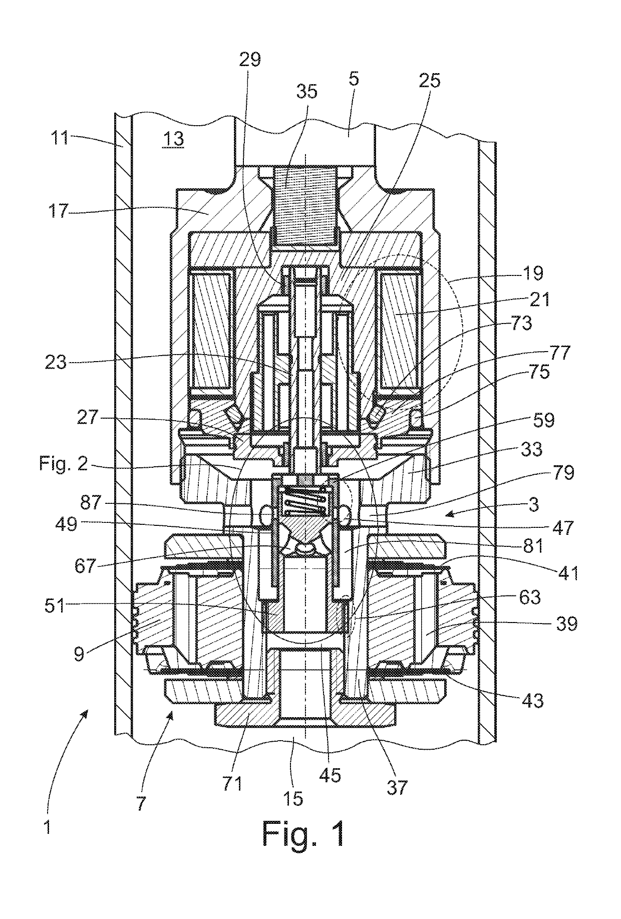
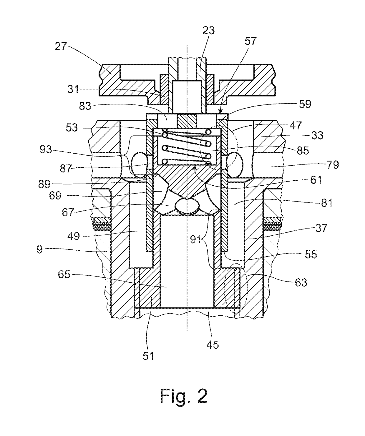
[0022]FIGS. 1 and 2 combined show a section from a vibration damper 1 of a selected type of construction in the region of a damping valve device 3 which is fixed to an axially moveable piston rod 5. The damping valve device 3 has a damping valve 7 constructed as piston valve, wherein an annular valve body 9 of the damping valve divides a cylinder 11 filled with damping medium into a working chamber 13 on the piston rod side and a working chamber 15 remote of the piston rod.

[0023]The damping valve device 3 has a pot-shaped housing 17 in which an actuator 19 is arranged. The actuator 19 comprises, inter alia, a coil 21 which exerts an axial displacing force on an armature 23. When excited, the coil 21 generates a displacing movement in move-out direction of the armature 23 out of the housing 17. The radial bearing support of the armature 23 is implemented in a back-iron 25 and in a pole disk 27 in each instance via bearing sleeves 29; 31, respectively. Accordingly, a base 33 which clo...


PUM


Abstract

A damping valve device includes an actuator which carries out an axial displacing movement on a sliding sleeve. The sliding sleeve, along with a fixed valve carrier, forms a slide valve which has two flow directions. The slide sleeve is impinged with damping medium on a front side and on a rear side in an incident flow direction, and the front side of the slide sleeve and rear side of the slide sleeve are impinged hydraulically in parallel by damping medium during the incident flow.

Description

PRIORITY CLAIM[0001]This is a U.S. national stage of application No. PCT / EP2016 / 058535, filed on Apr. 18, 2016. Priority is claimed on the following application: Country: Germany, Application No.: 10 2015 209 318.2, filed: May 21, 2015, the content of which is incorporated herein by reference in its entirety.FIELD OF THE INVENTION[0002]The present invention is directed to a damping valve device having an actuator which carries out an axial displacing movement on a sliding sleeve which forms part of an adjustable valve.BACKGROUND OF THE INVENTION[0003]An adjustable vibration damper which is marketed for, inter alia, motorcycles is known from US 2014 / 0116825 A1. In a motorcycle, the permissible overall length of the vibration damper is even more difficult to achieve compared with a passenger vehicle. It has turned out that an adjustable damping valve device having a conventional piston valve and, in addition, a parallel bypass opening as is shown in FIG. 13 of US 2014 / 0116825 A1is sui...

Claims


Application Information

Patent Timeline
Patent Type & Authority Patents(United States)
IPC IPC(8): F16F9/46
CPCF16F2230/0011F16F9/464
Inventor SCHMITT, STEFANMANGER, THOMASSCHWARZ, ALEXANDER
Owner ZF FRIEDRICHSHAFEN AG
Why Eureka
Try Eureka