Slurry mixer for a battery electrode

a battery electrode and slurry mixer technology, which is applied in the direction of rotary stirring mixers, electrode manufacturing processes, transportation and packaging, etc., can solve the problems of high labor intensity, high labor intensity, and easy deterioration of components, so as to reduce the rotational load during stirring, simplify the configuration of the high-speed stirring body, and uniform stirring operation

Active Publication Date: 2021-07-15
TSI CO LTD
View PDF0 Cites 8 Cited by
  • Summary
  • Abstract
  • Description
  • Claims
  • Application Information

AI Technical Summary

Benefits of technology

[0021]According to the slurry mixer for a battery electrode of the present invention having the above-described characteristic configuration, by causing a vortex while rotating the mixed material including the liquid material and the powdery material at a high speed using the high-speed stirring body rotating at a high speed and the low-speed stirring body rotating at a low speed, a uniform stirring operation may be performed. In addition, as the configuration of the high-speed stirring body is greatly simplified, a rotational load during stirring may be reduced as much as possible, and a rotation of the high-speed stirring body may be set at a high speed, and thereby greatly reducing the stirring time and increasing productivity.
[0022]In addition, according to the slurry mixer for a battery electrode of the present invention, since installation positions and the number of installed stirring rods of the high-speed stirring body may be increased or decreased, it is possible to achieve an optimum rotational load of the high-speed stirring body, which is differently applied depending on a particle size, a specific and a mixing ratio of materials to be mixed, and thereby a deterioration in the stirring efficiency may be prevented.
[0023]Further, according to the slurry mixer for a battery electrode of the present invention, the liquid material is fed into the container through the liquid injection nozzles provided in the cover during feeding, such that it is possible to wash the powdery

Problems solved by technology

However, the dispersing and feeding method is disadvantageous in that not only the feeding operation of the mixed material is troublesome but also the stirring time is very long, about 7 to 8 hours, such that productivity is very low.
Thereby, a minute error occurs in a mixing ratio between the materials, which may affect characteristics of the prepared slurry for manufacturing an electrode after stirring.
At t

Method used


Image

  • Slurry mixer for a battery electrode
  • Slurry mixer for a battery electrode
  • Slurry mixer for a battery electrode

Examples


Embodiment Construction

[0039]Hereinafter, preferred embodiments of the present invention will be described in detail with reference to the accompanying drawings.

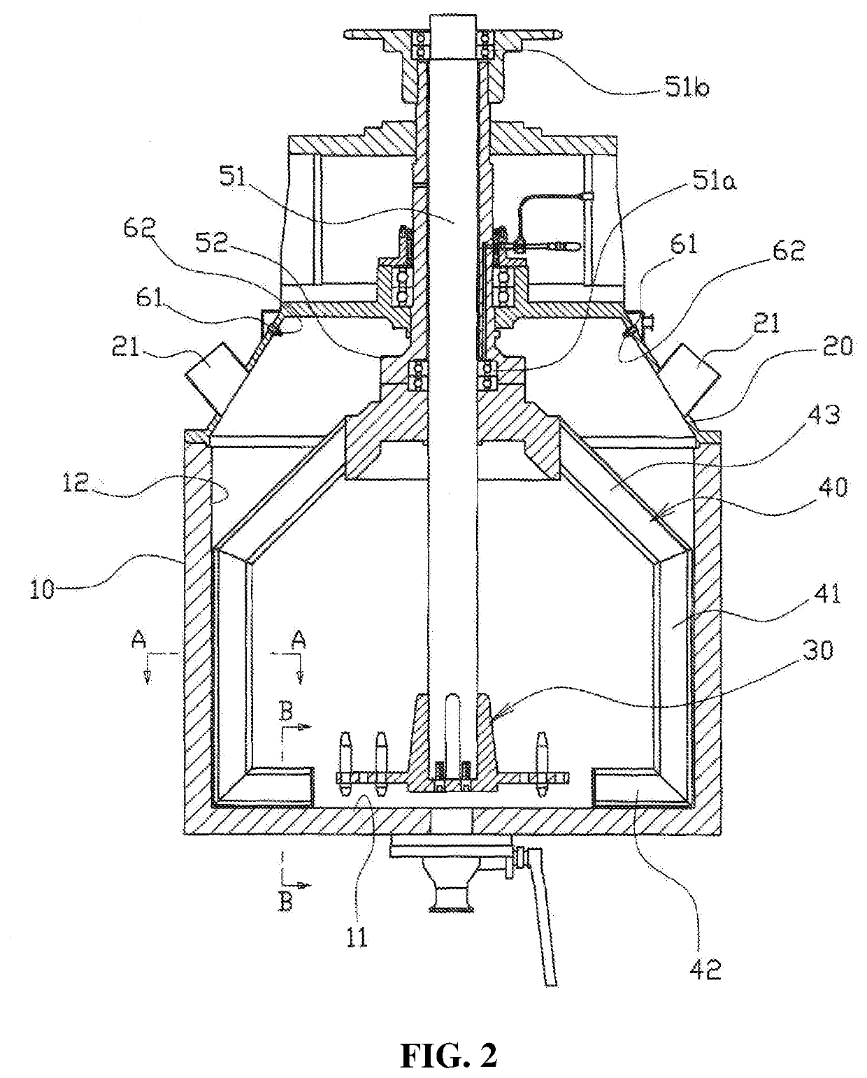
[0040]FIG. 2 is a cross-sectional view illustrating a slurry mixer for a battery electrode according to the present invention. As shown in FIG. 2, the slurry mixer includes a cylindrical container 10 in which a mixed material of liquid and powdery materials for preparing a slurry for a battery electrode may be received. The container 10 has a tubular shape whose upper portion is open, and includes a flat horizontal bottom surface 11, and an inner circumferential surface 12 vertically erected from an edge of the bottom surface 11.

[0041]The container 10 has a cover 20 which openably / closably covers the open upper portion thereof. The cover 20 is provided with a plurality of feed ports 21 which may feed the liquid material and the powdery material into the container 10.

[0042]The mixed material fed into the container 10 is uniformly stirred by a high-...


PUM

PropertyMeasurementUnit
Diameteraaaaaaaaaa
Speedaaaaaaaaaa

Abstract

A slurry mixer for a battery electrodecapable of maximally simplifying a configuration of a high-speed stirring body to minimize a rotational load, such that a stirring time of the slurry may be greatly reduced and productivity may be increased, preventing a powdery material from being accumulated on an upper side face and an upper surface of a low-speed stirring body, preventing a deterioration in a performance, failure and a reduction in a life span of a high-speed stirring shaft and bearing, and uniformly stirring mixed materials located at inner corners and a bottom of a container, thereby further increasing stirring efficiency.

Description

TECHNICAL FIELD[0001]The present invention relates to a slurry mixer for a battery electrode, and more particularly, to a slurry mixer for a battery electrode in which a mixed material of liquid and powdery materials may be dispersed during manufacturing of a slurry used for forming a battery electrode so as to achieve uniform mixing of the mixed material.BACKGROUND ART[0002]In recent years, using a battery that can be continuously used through recharging with electricity has been proposed as a solution to environmental pollution by reducing a use of fossil fuel and actively recycling a renewable energy. A secondary battery is universally employed as a power source of portable electronic devices such as a mobile phone, notebook computer or the like. In particular, secondary battery production has been significantly increased due to active development of electric vehicles.[0003]Among methods for manufacturing such a secondary battery, there is a method of using application, in which ...

Claims


Application Information

Patent Timeline
IPC IPC(8): B01F7/16B01F3/12B01F15/06B01F7/00B01F15/02H01M4/04
CPCB01F7/166B01F3/1221B01F15/065B01F7/007B01F15/0203B01F2015/00084B01F7/00208B01F7/00341B01F7/00316H01M4/04B01F2003/1257B01F15/0254Y02E60/10B01F23/53B01F27/0721B01F27/0725B01F27/071B01F27/1121B01F27/091B01F27/84B01F33/5024B01F2035/352B01F35/712B01F35/7179B01F27/62B01F27/113B01F27/2122B01F27/11253B01F35/92B01F23/565B01F2035/98B01F2035/351
Inventor PYO, IN SIKAN, CHANG HEEKANG, SHIN GU
Owner TSI CO LTD
Why Eureka
Try Eureka