Bicycle component positioning device

a positioning device and bicycle technology, applied in the direction of mechanical control devices, gearing, instruments, etc., can solve the problems of uneven shifting, repeated cable stretching, minor misalignment of the derailleur, etc., and achieve the effect of smooth movement and reliabl

Inactive Publication Date: 2014-07-15
SHIMANO INC
View PDF63 Cites 28 Cited by
  • Summary
  • Abstract
  • Description
  • Claims
  • Application Information

AI Technical Summary

Benefits of technology

[0008]One object of the present invention is to provide a bicycle component positioning device, which moves smoothly and reliably, yet is reliably retained in different positions.
[0010]Another object of the present invention is to provide a bicycle component positioning device, which is relatively simple and inexpensive to manufacture and / or assemble.

Problems solved by technology

With these conventional derailleurs, shifting is not always as smooth and reliable as desired by some riders.
Moreover, the control cable is always held in tension by the spring, which leads to continued cable stretching.
Continued cable stretching leads to frequent adjustment of the derailleur and / or shifter or minor misalignment of the derailleur.
Furthermore, conventional derailleurs can be relatively complicated and expensive to manufacture, assemble, to mount to the bicycle and / or adjust.
Thus, a relatively strong retaining force must be provided, which can be relatively difficult to overcome when moving the lever(s).
Additionally, when the shifting device is actuated to wind the cable, an even stronger force is often required than during an unwinding operating due to the derailleur biasing member.
In either case, the shifting action(s) may feel awkward to some individuals.
Also, with these conventional shifters, shifting is not always as smooth and reliable as desired by some riders.
Moreover, conventional shifters can be relatively complicated and expensive to manufacture, assemble, to mount to the bicycle and / or adjust.

Method used


Image

  • Bicycle component positioning device
  • Bicycle component positioning device
  • Bicycle component positioning device

Examples


Embodiment Construction

[0068]Selected embodiments of the present invention will now be explained with reference to the drawings. It will be apparent to those skilled in the art from this disclosure that the following descriptions of the embodiments of the present invention are provided for illustration only and not for the purpose of limiting the invention as defined by the appended claims and their equivalents.

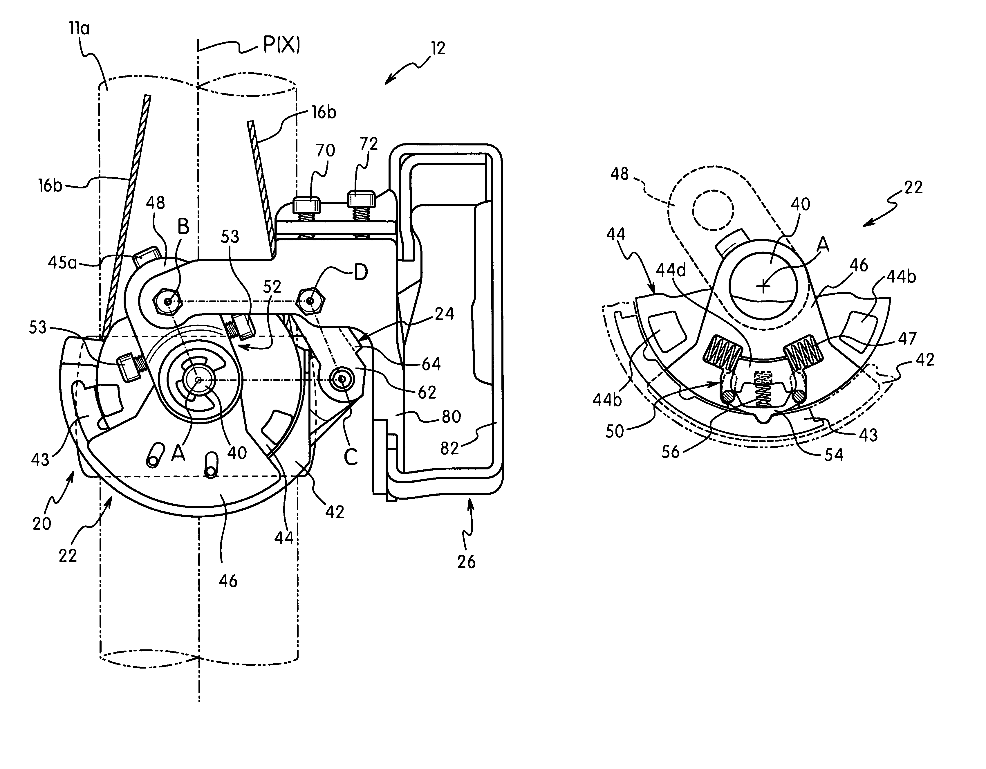
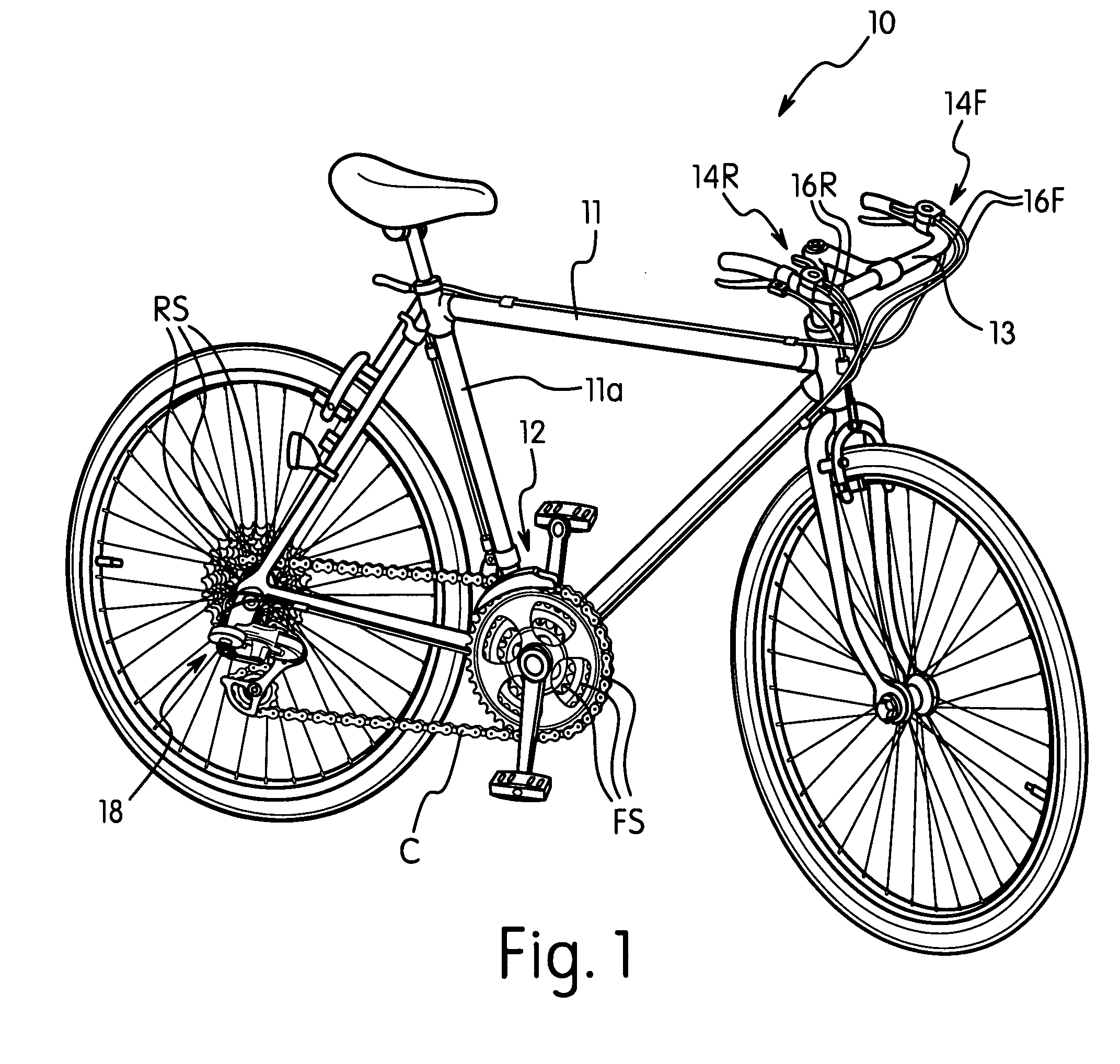
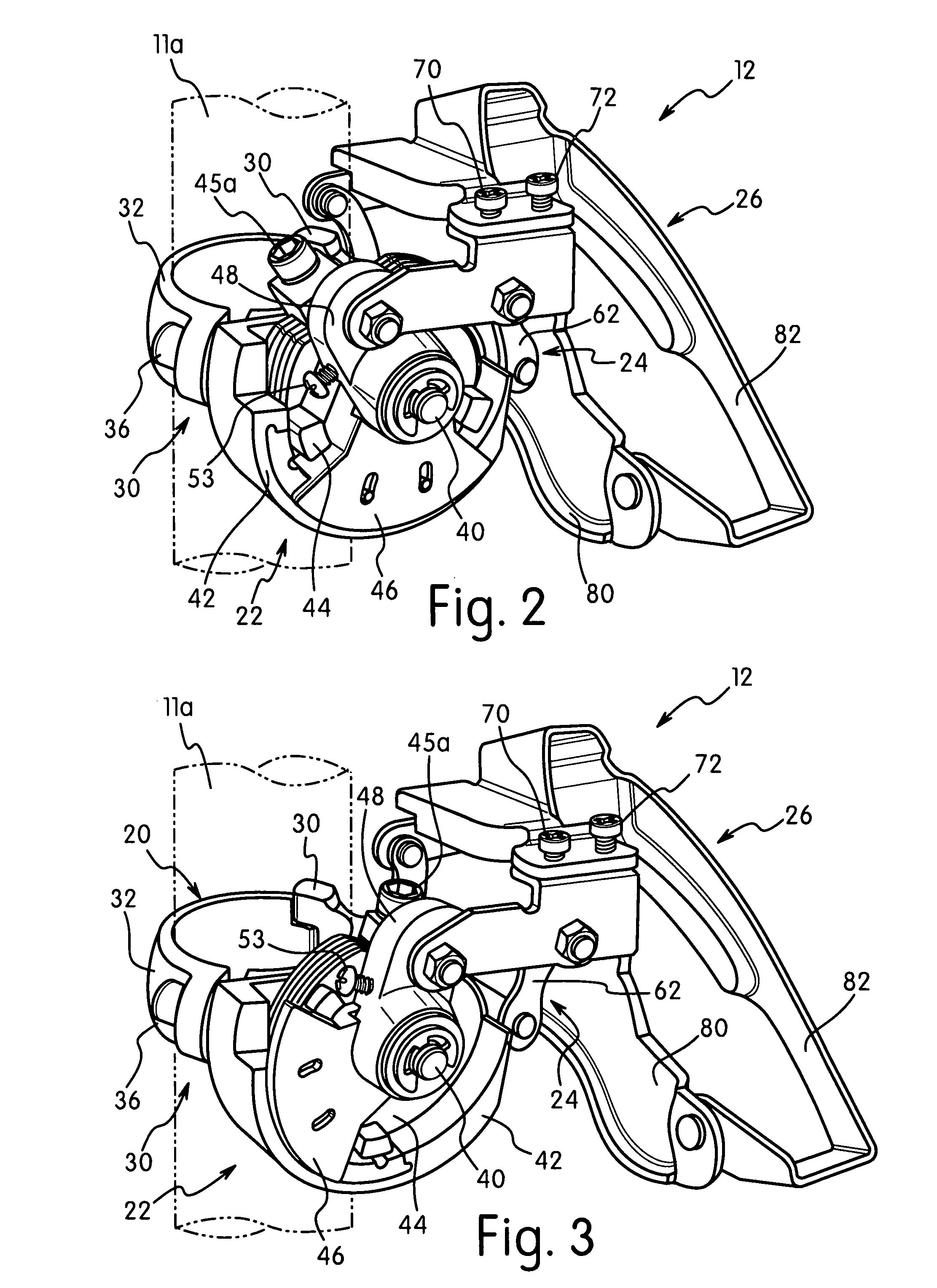
[0069]Referring initially to FIGS. 1-3, a bicycle 10 is illustrated with a front shifting system and a rear shifting system coupled thereto in accordance with the present invention. The front shifting system includes front derailleur 12 and a front shifter 14F operatively coupled to the front derailleur 12 via a pair of front shift control cables 16F to move a chain C between at least two (three illustrated herein) front sprockets or chain rings FS. Similarly, the rear shifting system includes a rear derailleur 18 and a rear shifter 14R operatively coupled to the rear derailleur 18 via a pair of re...


PUM


Abstract

A bicycle component positioning device includes a fixed member, an operating member and a positioning mechanism. The operating member has an input portion and an output portion. The positioning mechanism is operatively disposed between the operating member and the fixed member. The positioning mechanism includes a positioning member that is movable between a first position in which the positioning member is engaged with the fixed member and a second position in which the positioning member is disengaged from the fixed member. The positioning member is held in engagement with the fixed member in the first position by the input portion when the input portion is in an operating position. The positioning member is movable from the first position to the second position upon movement of the input portion from at least one of the operating positions.

Description

BACKGROUND OF THE INVENTION[0001]1. Field of the Invention[0002]This invention generally relates to a bicycle component positioning device. More specifically, the present invention relates to a bicycle component positioning device for a bicycle component such as a derailleur or shifter, which has the same relatively easy action when moved in two opposite directions, yet is reliably retained.[0003]2. Background Information[0004]Bicycling is becoming an increasingly more popular form of recreation as well as a means of transportation. Moreover, bicycling has become a very popular competitive sport for both amateurs and professionals. Whether the bicycle is used for recreation, transportation or competition, the bicycle industry is constantly improving the various components of the bicycle such as derailleurs and shifters.[0005]A bicycle derailleur basically includes a base, a chain guide and a linkage coupled between the base and the chain guide to move the chain guide between various...

Claims


Application Information

Patent Timeline
Patent Type & Authority Patents(United States)
IPC IPC(8): B62M9/1344
CPCB62M9/1344Y10T74/20678Y10T74/20287Y10T74/20438Y10T74/20043
Inventor KAWAKAMI, TATSUYAIIZUKA, ATSUSHI
Owner SHIMANO INC
Why Eureka
Try Eureka