Spiral wound element and seal assembly

a technology of seal assembly and wound element, which is applied in the direction of membranes, filtration separation, separation processes, etc., can solve the problems of overall energy efficiency of separation, bypassing also reducing the effective feed fluid pressure, etc., to achieve rapid and easy flushing of air and improve energy consumption

Inactive Publication Date: 2014-07-15
DOW GLOBAL TECH LLC
View PDF46 Cites 36 Cited by
  • Summary
  • Abstract
  • Description
  • Claims
  • Application Information

AI Technical Summary

Benefits of technology

[0003]The present invention is directed toward a spiral wound assembly including a spiral wound element and a seal assembly. The seal assembly comprises: a seal disposed about a portion of an outer periphery of the element, a secondary pathway and a valve that selectively permits fluid flow through the secondary pathway. Several embodiments provide a means for providing selected fluid flow through an annular pathway located between an element and a surrounding pressure vessel which offers improved energy consumption as compared with the aforementioned techniques. Selected embodiments allow an installed pressure vessel to be quickly and easily flushed of air during start-up. Many different embodiments are described.

Problems solved by technology

While the use of such a bypass reduces fluid stagnation in areas surrounding the elements, the bypass also reduces the effective feed fluid pressure and overall energy efficiency of the separation.

Method used


Image

  • Spiral wound element and seal assembly
  • Spiral wound element and seal assembly
  • Spiral wound element and seal assembly

Examples


Embodiment Construction

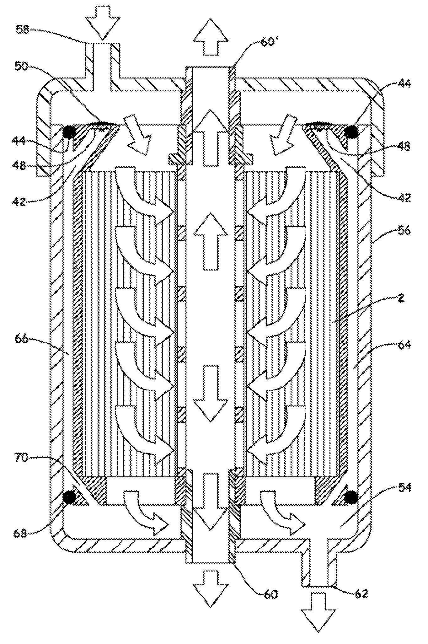
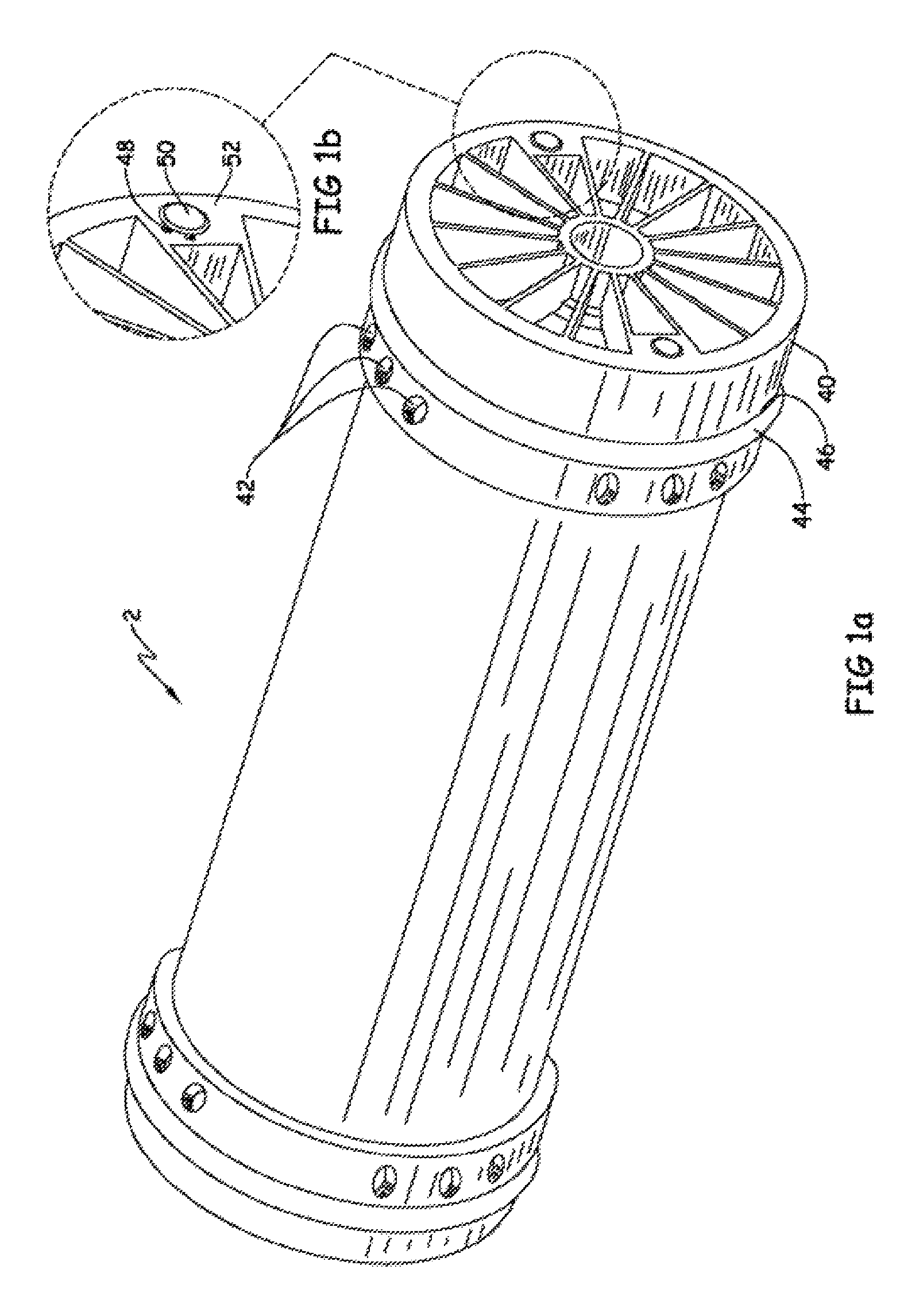
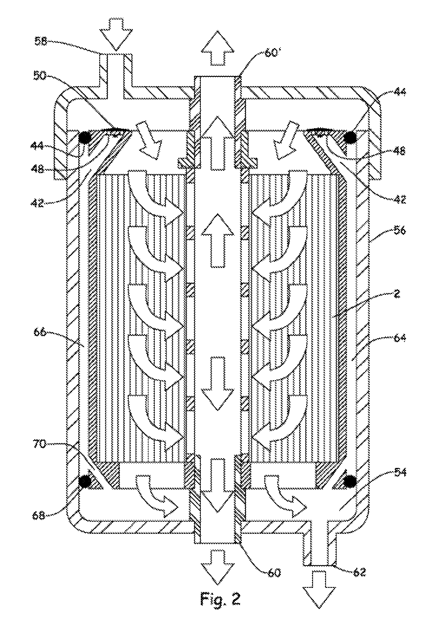
[0010]In one embodiment the present invention includes a spiral wound assembly comprising a spiral wound element and a first seal assembly. The first seal assembly includes: i) a ring-shaped seal disposed about a portion of the outer periphery of the element, ii) a secondary pathway, and iii) a valve that selectively permits fluid flow through the secondary pathway. FIG. 1 illustrates one such embodiment including a spiral wound element (2) having an outer periphery and an end cap (40). A first seal assembly is incorporated into the end cap (40) and includes a seal (44) disposed within an annular groove (46) about the circumference of the end cap (40). A secondary pathway is provided in the end cap (40) and provides a route for fluid to bypass the seal (44). More specifically, the secondary pathway comprises one or more ports (42) located about the outer periphery of the end cap (40) which join to form one or more common outlets (48) located on the outer face (52) of the end cap (40...


PUM

PropertyMeasurementUnit
lengthaaaaaaaaaa
diameteraaaaaaaaaa
diameteraaaaaaaaaa

Abstract

A spiral wound element and a seal assembly comprising: a ring-shaped seal disposed about a portion of an outer periphery of the element, a secondary pathway and a valve that selectively permits fluid flow through the secondary pathway.

Description

FIELD OF THE INVENTION[0001]The present invention is directed toward spiral wound elements and seal assemblies.DESCRIPTION OF THE RELATED ART[0002]Spiral wound assemblies are used in a wide variety of fluid separations. In a conventional embodiment, one or more spiral wound elements are serially arranged within a pressure vessel. During operation pressurized feed fluid is introduced into the vessel, passes through the elements and exits the vessel in at least two streams: concentrate and permeate. In order to restrict feed fluid from bypassing the elements within the vessel, seals are positioned between the outer periphery of the elements and the inner periphery of the vessel. Representative examples are described in: US 2011 / 0174713, US 2010 / 0147761, U.S. Pat. Nos. 7,198,719, 6,299,772, 6,224,767, and WO 2010 / 090251. In some embodiments, seal assemblies are equipped with a bypass that permits limited feed fluid to flow around the elements, e.g. see U.S. Pat. Nos. 7,208,088, and 5,1...

Claims


Application Information

Patent Timeline
Patent Type & Authority Patents(United States)
IPC IPC(8): B01D29/66B01D63/10B01D63/12B01D65/02C02F1/44C02F103/08B01D53/22
CPCC02F1/44C02F2201/004C02F1/442B01D63/10B01D2313/04B01D2321/02B01D63/12C02F1/444B01D2313/08B01D65/02C02F2103/08B01D2313/18C02F1/441B01D2313/083B01D2053/221B01D63/107B01D2313/041B01D2313/042
Inventor JOHNSON, JON E.MITTAG, MATTHEW D.
Owner DOW GLOBAL TECH LLC
Why Eureka
Try Eureka