Method and device for driving a display device with line-wise dynamic addressing

a display device and dynamic addressing technology, applied in the direction of electric digital data processing, instruments, computing, etc., can solve the problems of electromagnetic radiation in the actual plasma technology, inability to work properly, and inefficient appliance of jitter, etc., to achieve simple handling of signal dependencies, broaden the emi spectrum, and reduce the effect of jitter

Inactive Publication Date: 2014-07-15
THOMSON LICENSING SA
View PDF27 Cites 0 Cited by
  • Summary
  • Abstract
  • Description
  • Claims
  • Application Information

AI Technical Summary

Benefits of technology

[0032]The major advantage of the present invention is that the loading clock of the data drivers may be matched exactly to the addressing duration. Such different clocking broadens the spectrum of the EMI radiation so that the norm limitations can be fulfilled.
[0033]In the remainder of the description, loading speed and loading frequency are used indifferently for designating loading frequency. In the same manner, addressing speed and addressing frequency are used for designating addressing frequency.
[0034]The loading frequency may depend on the presence of a priming signal. Since the addressing frequency varies with the presence of the priming signal, also the loading frequency will do so. Thus, the application of a priming signal has to be regarded for controlling the loading frequency.
[0035]The loading frequency may vary with the line number of the screen of the display device (e.g. vertical panel behaviour). Specifically, since the addressing frequency continuously varies with the line number, also the loading frequency changes continuously so that the EMI spectrum is broadened.
[0036]The addressing frequency may be changed in dependence on a line number by using a first look up table (LUT). Similarly, since the loading frequency may be changed in dependence on the line number by using a second LUT. Such LUTs enable a simple handling of signal dependencies.

Problems solved by technology

However, the electronic parts of the actual plasma technology give rise to electromagnetic radiation.
This filtering is really mandatory since if the front filter is removed from a plasma panel, even an IR remote control is not able to work properly.
Such appliance of jitter is not very efficient.
Since the efficiency of the writing operation is linked to the capacity effect of the panel, this could change with the delay to the sustain operation.

Method used


Image

  • Method and device for driving a display device with line-wise dynamic addressing
  • Method and device for driving a display device with line-wise dynamic addressing
  • Method and device for driving a display device with line-wise dynamic addressing

Examples


Embodiment Construction

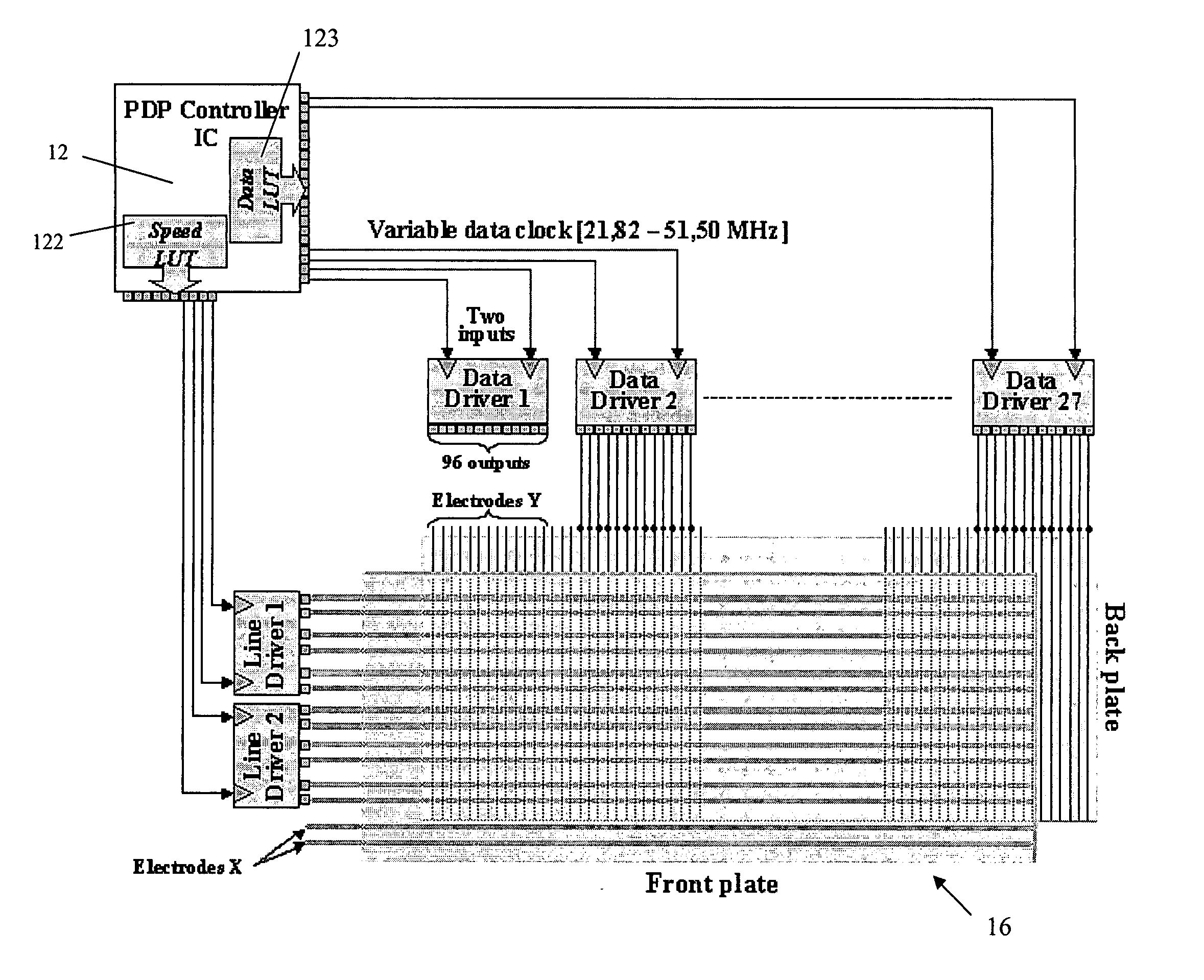
[0049]The main idea of the present invention is to adapt the loading speed precisely to the addressing period. A preferred embodiment shall be presented by the way of the example of FIG. 5, wherein the sub-fields are primed.

[0050]

Line 0:1.35 μs  35.6 MHzLine 25:1.23 μs 39.03 MHzLine 50:1.13 μs 42.49 MHzLine 75:1.05 μs 45.72 MHzLine 100:0.99 μs 48.49 MHzLine 125:0.95 μs 50.54 MHzLine 150:0.93 μs 51.62 MHzLine 175:0.93 μs 51.62 MHzLine 200:0.94 μs 51.07 MHzLine 225:0.97 μs 49.49 MHzLine 250:1.01 μs 47.53 MHzLine 275:1.06 μs 45.29 MHzLine 300:1.14 μs 42.11 MHzLine 325:1.23 μs 39.03 MHzLine 350:1.34 μs 35.83 MHzLine 375:1.48 μs 32.43 MHzLine 400:1.63 μs 29.45 MHzLine 425:1.81 μs 26.51 MHzLine 480:2.20 μs 21.82 MHz

[0051]In the list, the first column represents a line to be addressed, the second column the required speed addressing time per line and the last one the current data clock to be used at the data driver for the corresponding line. In FIG. 7 the data clock for the case of a prim...


PUM


Abstract

The EMI spectrum of a display device is to comply with respective norms. Therefore, the clock for loading data into data drivers of a display panel is designed to be variable. Consequently, the electromagnetic radiation produced by the loading clock is broadened thereby reducing the peak amplitude. Thus, the limitations of radiation norms can be complied with.

Description

[0001]This application claims the benefit, under 35 U.S.C. §1.19 of European Patent Application 04291751.8, filed Jul. 9, 2004.FIELD OF THE INVENTION[0002]The present invention relates to a method for driving a display device having a plurality of cells or pixels by loading addressing data into a data driver at a loading frequency and applying an addressing signal to at least one of said plurality of cells or pixels for an addressing time period corresponding to an addressing frequency. Furthermore, the present invention relates to a corresponding device for driving a display device.BACKGROUND OF THE INVENTION[0003]Today, the Plasma technology makes it possible to achieve flat colour panels of large size and with very limited depth without any viewing angle constraints. The size of the displays may be much larger than the classical CRT picture tubes.[0004]Referring to the last generation of European TV, a lot of work has been done to improve its picture quality. Consequently, a new ...

Claims


Application Information

Patent Timeline
Patent Type & Authority Patents(United States)
IPC IPC(8): G06F3/038G09G3/288G09G3/293G09G3/296
CPCG09G3/296G09G3/293G09G2310/0218G09G2330/06G09G3/291
Inventor WEITBRUCH, SEBASTIENTHEBAULT, CEDRICSCHWEER, RAINER
Owner THOMSON LICENSING SA
Why Eureka
Try Eureka