
Imaging lens, image pickup apparatus, and portable terminal

a technology of image pickup and portable terminal, which is applied in the field of image pickup and image pickup, can solve the problems of insufficient correction of spherical aberration coefficient and somatic aberration, inability to achieve good performance, and inability to deal with the increase in pixel number of the lens, etc., and achieves the effect of well corrected

Active Publication Date: 2014-07-15
KONICA MINOLTA OPTO
View PDF7 Cites 4 Cited by
  • Summary
  • Abstract
  • Description
  • Claims
  • Application Information

AI Technical Summary

Benefits of technology

The present invention provides a small five-lens structure imaging lens that has well-corrected aberrations. An image pickup apparatus and a portable terminal equipped with this lens are also provided.

Problems solved by technology

However, in the imaging lens disclosed in Patent Document 1, the first lens through the third lens bear almost all the refractive power of the entire lens system, and the fourth lens and the fifth lens have only a function as an image plane correction lens having a weak refractive power, and aberration correction is thus not sufficient, and in addition, there is an issue that, in the case of further shortening the overall lens length, the lens cannot deal with increase in pixel number because of decrease in performance.
In addition, in the imaging lens disclosed in Patent Document 2, since the front group made up of a first lens and a second lens is made to have spherical surfaces, the spherical aberration coefficient and the somatic aberration are not sufficiently corrected, whereby good performance cannot be obtained.
In addition, both of the front group and the rear group containing the third lens and after have positive refractive powers; thus, the principal point position of the optical system is more on the image side and the back focus is accordingly longer than the telephoto type configuration having negative refractive power in the rear group, whereby it is disadvantageous for downsizing.

Method used


Image

  • Imaging lens, image pickup apparatus, and portable terminal
  • Imaging lens, image pickup apparatus, and portable terminal
  • Imaging lens, image pickup apparatus, and portable terminal

Examples


example 1

The lens data of an imaging lens of Example 1 are as follows.

[0151]

f = 3.68 mm, fB = 0.29 mm, F = 2.45, 2Y = 5.53 mmENTP = 0.37 mm, EXTP = −2.48 mm,H1 = −0.84 mm, H2 = −3.4 mmEffective RadiusSurface No.R (mm)D (mm)Ndνd(mm)1*1.5510.431.5447056.20.882*48.2370.050.743 (aperture)∞0.000.694*2.6060.181.6320023.40.715*1.4110.790.746*5.4180.321.5830030.01.177*2.9200.121.498*−232.1170.881.5447056.21.709*−1.5630.551.7410* 2.2440.431.5305055.72.3511* 0.970.502.6412 ∞0.151.5163064.12.8013 ∞2.84Aspherical Coefficient:1st SurfaceK = 0.41415E+00A4 = −0.37689E−02A6 = 0.17668E−01A8 = −0.23233E−01A10 = 0.33420E−02A12 = 0.45468E−012nd SurfaceK = 0.50000E+02A4 = 0.56716E−01A6 = −0.23292E−01A8 = 0.21713E−01A10 = −0.15444E−01A12 = 0.64215E−014th SurfaceK = −0.11747E+02A4 = 0.59161E−02A6 = 0.38159E−01A8 = −0.45582E−01A10 = 0.24607E−02A12 = 0.17962E−015th SurfaceK = −0.39137E+01A4 = 0.50498E−01A6 = 0.84768E−01A8 = −0.61733E−01A10 = −0.44361E−02A12 = 0.59071E−016th SurfaceK = 0.80090E+01A4 = −0.13885E+00A6 ...

example 2

The lens data of an imaging lens of Example 2 are as follows.

[0153]

f = 3.68 mm, fB = 0.23 mm, F = 2.45, 2Y = 5.53 mmENTP = 0.33 mm, EXTP = −2.44 mm,H1 = −1.06 mm, H2 = −3.45 mmSurface No.R (mm)D (mm)NdνdEffective Radius (mm)1*1.6300.381.5447056.20.872*289.4020.050.763 (aperture)∞0.000.704*2.1230.161.6320023.40.725*1.2510.840.756*2.4050.221.6320023.41.277*1.8730.151.508*11.6511.071.5447056.21.789*−1.6630.521.8110* 3.8070.421.5305055.72.0111* 1.0870.502.5212 ∞0.151.5163064.12.7913 ∞2.83Aspherical Coefficient:1st SurfaceK = 0.38758E+00A3 = −0.79256E−04A4 = −0.41120E−03A5 = −0.83837E−04A6 = 0.24258E−01A7 = −0.38553E−04A8 = −0.55840E−01A9 = −0.38330E−04A10 = 0.57615E−01A11 = −0.89253E−04A12 = −0.11269E−03A13 = −0.11847E−03A14 = −0.93213E−04A15 = −0.23363E−04A16 = 0.10435E−03A17 = 0.30267E−03A18 = 0.58370E−03A19 = 0.95866E−03A20 = 0.14382E−022nd SurfaceK = 0.11688E+05A3 = 0.78044E−04A4 = 0.64523E−01A5 = −0.10025E−04A6 = −0.43096E−01A7 = −0.27277E−04A8 = 0.15447E−01A9 = −0.21365E−04A10 = 0...

example 3

The lens data of an imaging lens of Example 3 are as follows.

[0155]

f = 3.68 mm, fB = 0.24 mm, F = 2.45, 2Y = 5.53 mmENTP = 0.37 mm, EXTP = −2.43 mm,H1 = −1.01 mm, H2 = −3.44 mmSurface No.R (mm)D (mm)NdνdEffective Radius (mm)1*1.5650.421.5447056.20.872*67.1330.050.753 (aperture)∞0.000.694*2.8120.231.6320023.40.715*1.4430.700.756*4.9180.411.6320023.41.197*3.2390.151.538*48.9120.911.5447056.21.789*−1.6330.451.7910* 3.0650.471.5305055.72.0911* 1.0700.502.4812 ∞0.151.5163064.12.7713 ∞2.81Aspherical Coefficient:1st SurfaceK = 0.33365E+00A3 = 0.10687E−02A4 = −0.10276E−02A5 = −0.38013E−03A6 = 0.23951E−01A7 = 0.25771E−02A8 = −0.35839E−01A9 = 0.35017E−02A10 = 0.44681E−01A11 = 0.96501E−03A12 = −0.69520E−03A13 = −0.20433E−02A14 = −0.26936E−02A15 = −0.23462E−02A16 = −0.79845E−03A17 = 0.20702E−02A18 = 0.63322E−02A19 = 0.11943E−01A20 = 0.18806E−012nd SurfaceK = −0.28795E+03A3 = −0.12360E−03A4 = 0.79803E−01A5 = 0.15462E−02A6 = −0.60149E−01A7 = 0.41253E−02A8 = 0.37670E−01A9 = 0.42893E−02A10 = 0.9126...


PUM


Abstract

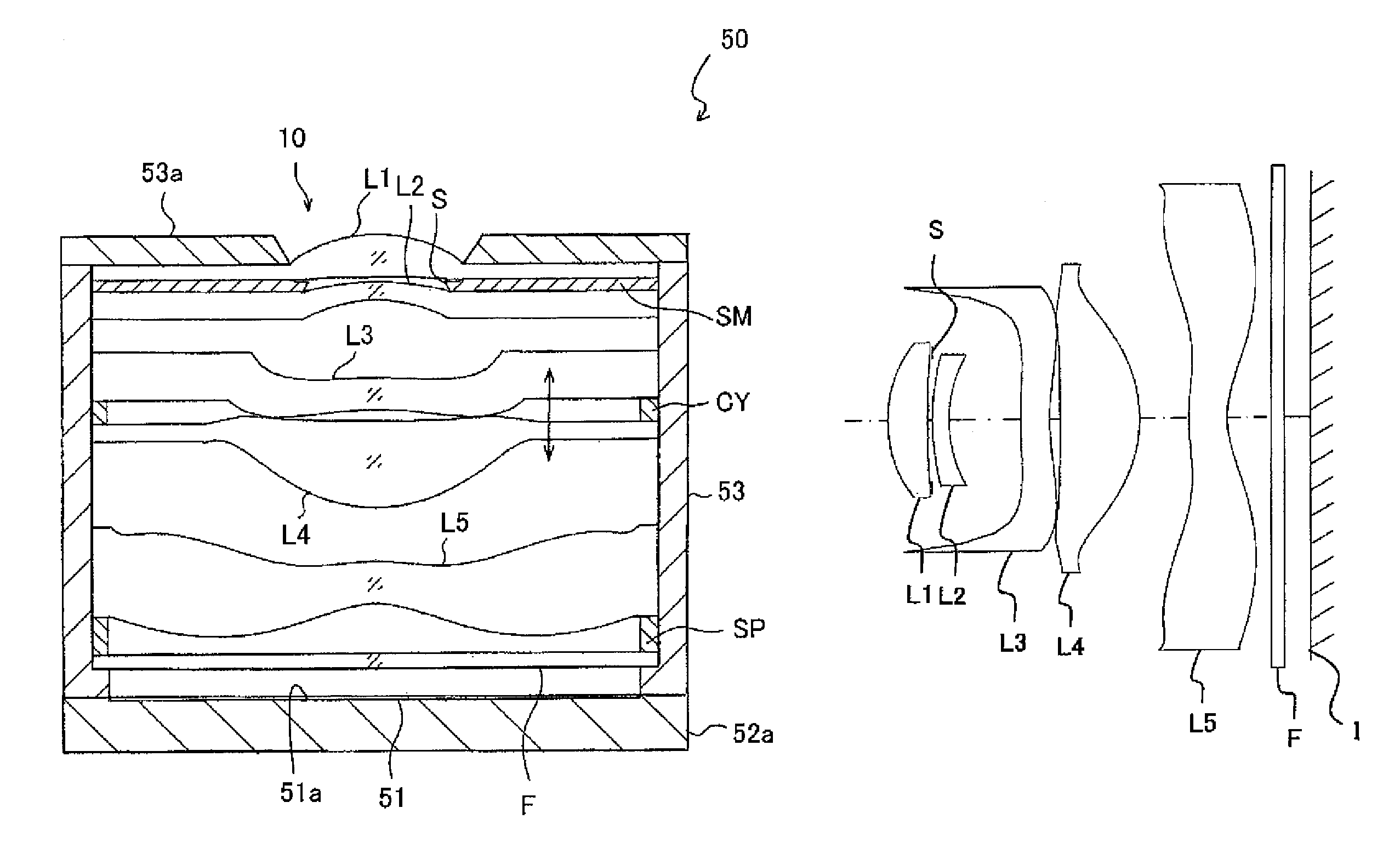
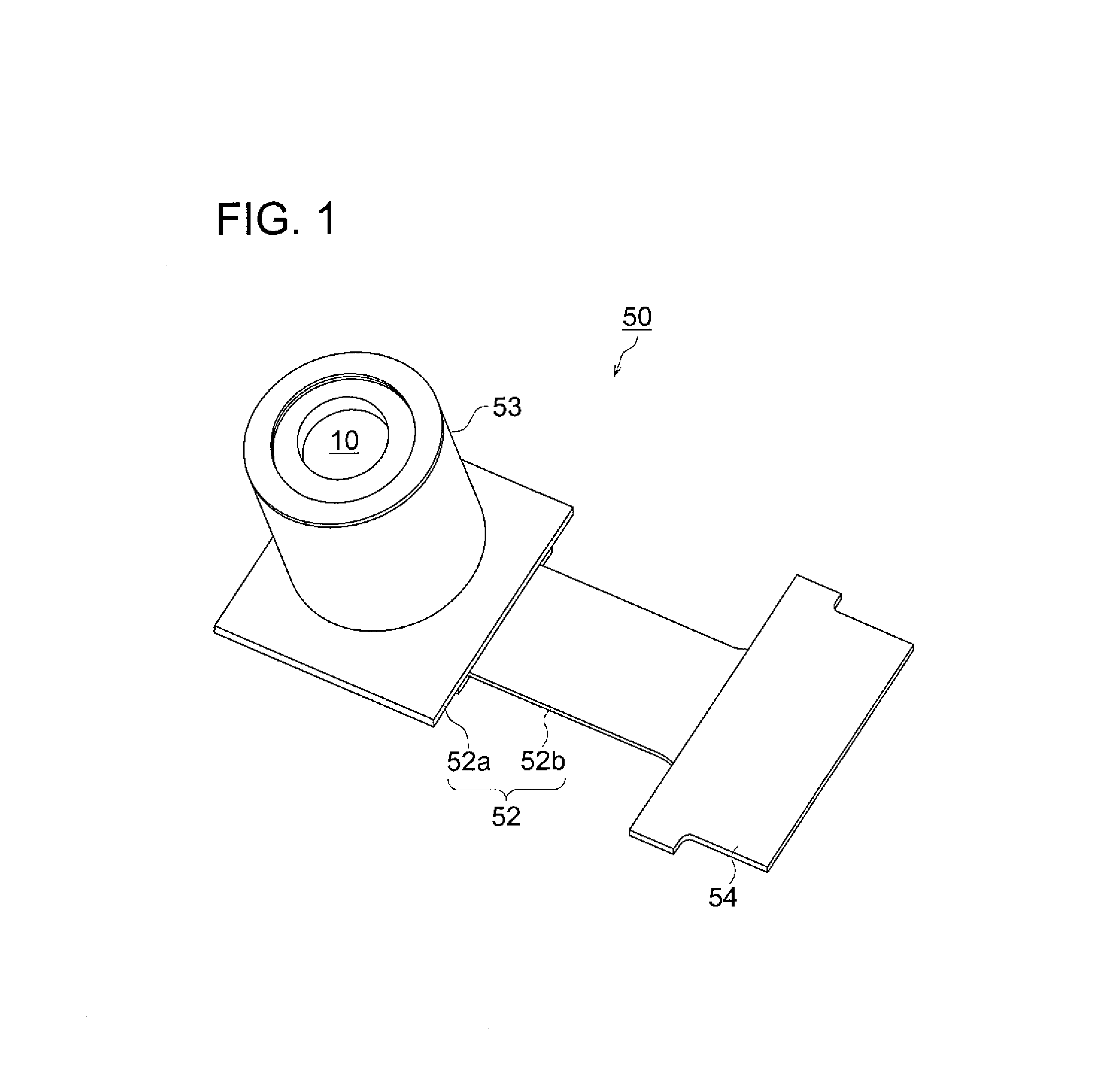
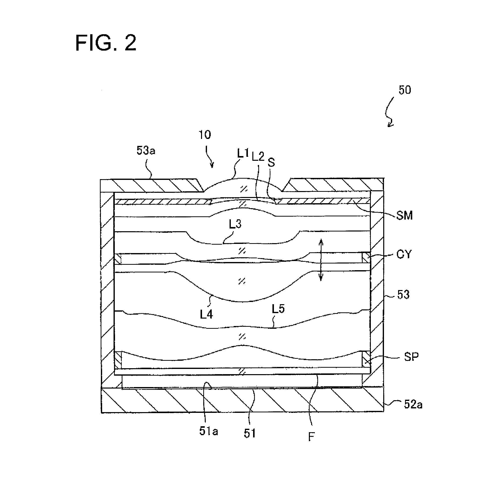
Provided is an imaging lens, and also provided are an image pickup apparatus and a portable terminal both equipped with the imaging lens. The imaging lens includes in order: a positive first lens having a convex object-side surface; a negative second lens having a concave image-side surface; a negative meniscus-shaped third lens having a convex object-side surface; a positive fourth lens having a convex image-side surface; and a negative fifth lens having a concave image-side surface. The image-side surface of the fifth lens is aspherical and has an inflection point at a position of the optical axis. The third and the fourth lenses are integrally moved to focus, and the following conditional relation is satisfied: 0.75<f34 / f<1.30, where f34 is the combined focal length of the third lens and the fourth lens, and f is the focal length of the entire system of the imaging lens.

Description

RELATED APPLICATIONS[0001]This is a U.S. National Phase Application under 35 USC 371 of International Application PCT / JP2010 / 073145 filed on Dec. 22, 2010.[0002]This application claims the priority of Japanese Application No. 2010-004577 filed Jan. 13, 2010, the entire content of which is hereby incorporated by reference.TECHNICAL FIELD[0003]The present invention relates to imaging lenses suitable for a small sized image pickup apparatus using a solid state image sensor such as a CCD image sensor or a CMOS image sensor, image pickup apparatuses, and portable terminals using the same.BACKGROUND ART[0004]In recent years, along with improvement in performance and downsizing of imaging elements using solid state image sensors such as a CCD (Charge Coupled Device) image sensor or a CMOS(Complementary Metal Oxide Semiconductor) image sensor, portable phones and portable information terminals equipped with image pickup apparatuses are becoming widely used. Thus, imaging lenses to be built ...

Claims


Application Information

Patent Timeline
Patent Type & Authority Patents(United States)
IPC IPC(8): G02B3/02G02B13/18
CPCG02B13/0045G02B13/18
Inventor SANO, EIGONISHIDA, MAIKO
Owner KONICA MINOLTA OPTO
Learn More