Eureka AIR delivers breakthrough ideas for toughest innovation challenges, trusted by R&D personnel around the world.

Image-recognition method for assisting ophthalmic examination instrument

a technology of image recognition and ophthalmology, applied in the field of image recognition, can solve problems such as difficulty in assisting examiners to clearly recognize, and achieve the effects of increasing luminance contrast, increasing sharpness and luminance contrast, and increasing luminance contras

Active Publication Date: 2014-07-15
CRYSTALVUE MEDICAL
View PDF11 Cites 0 Cited by
  • Summary
  • Abstract
  • Description
  • Claims
  • Application Information

AI Technical Summary

Benefits of technology

[0005]A primary object of the present invention is to provide an image-recognition assisting method for optimizing a split image formed by a split-image focusing screen on, for example, a fundus image captured by a conventional ophthalmic examination instrument, so that the split image has increased sharpness and luminance contrast for an examiner to easily recognize two vertically offset rectangular image parts of the split image and focus the fundus image by aligning the two offset rectangular image parts with each other.
[0006]To achieve the above and other objects, the image-recognition assisting method according to the present invention includes the steps of using an examination instrument to generate an image having a split-image area formed thereon; setting a region-of-interest (ROI) around the split-image area of the generated image; performing a pixel luminance addition processing on the ROI, so that all pixels in the ROI have increased luminance contrast; and performing a contrast correction on the ROI having increased luminance contrast, so that the luminance contrast between the split-image area and the area surrounding the split-image area in the ROI is further increased.
[0007]In the method of the present invention, the examination instrument is an ophthalmic examination instrument for examining an examinee's retina; the ROI can be defined by a value manually set by an examiner for forming a required size of the ROI or by one of preset values in the examination instrument; and the pixel luminance addition processing increases the luminance contrast of all pixels in the ROI by adding luminance values of pixels surrounding each pixel to a luminance value of the surround pixel.
[0008]In a preferred embodiment of the present invention, the contrast correction is implemented by Gamma correction. The Gamma correction further increases the luminance of pixels having a relatively higher luminance value and further reduces the luminance of pixels having a relatively lower luminance value, so that an increased and clearly recognizable luminance contrast is created between the split-image area and the surrounding area in the ROI for the examiner to easily and correctly align the two offset image parts in the split-image area with each other to achieve the purpose of focusing the examination instrument.
[0009]Therefore, the method of the present invention is characterized in defining an ROI around a vague and dark split-image area on an image generated by an ophthalmic examination instrument, performing the pixel luminance addition processing on adjoining pixels in the ROI, and performing Gamma correction to largely sharpen the offset rectangular image parts in the split-image area and the area surrounding the split-image area to create a strong contrast between them. Therefore, the examiner can easily recognize the two offset rectangular image parts of the split image and make necessary adjustment to align them with each other to achieve optimized focusing of the examination instrument. And, the problem of a vague split image formed by the conventional split-image focusing screen can be overcome.

Problems solved by technology

It is very difficult for the examiner to clearly recognize the positions of the two rectangular image parts and accurately align them with each other to achieve the purpose of focusing the examination instrument.

Method used


Image

  • Image-recognition method for assisting ophthalmic examination instrument
  • Image-recognition method for assisting ophthalmic examination instrument
  • Image-recognition method for assisting ophthalmic examination instrument

Examples


Embodiment Construction

[0018]The present invention will now be described with a preferred embodiment thereof and with reference to the accompanying drawings.

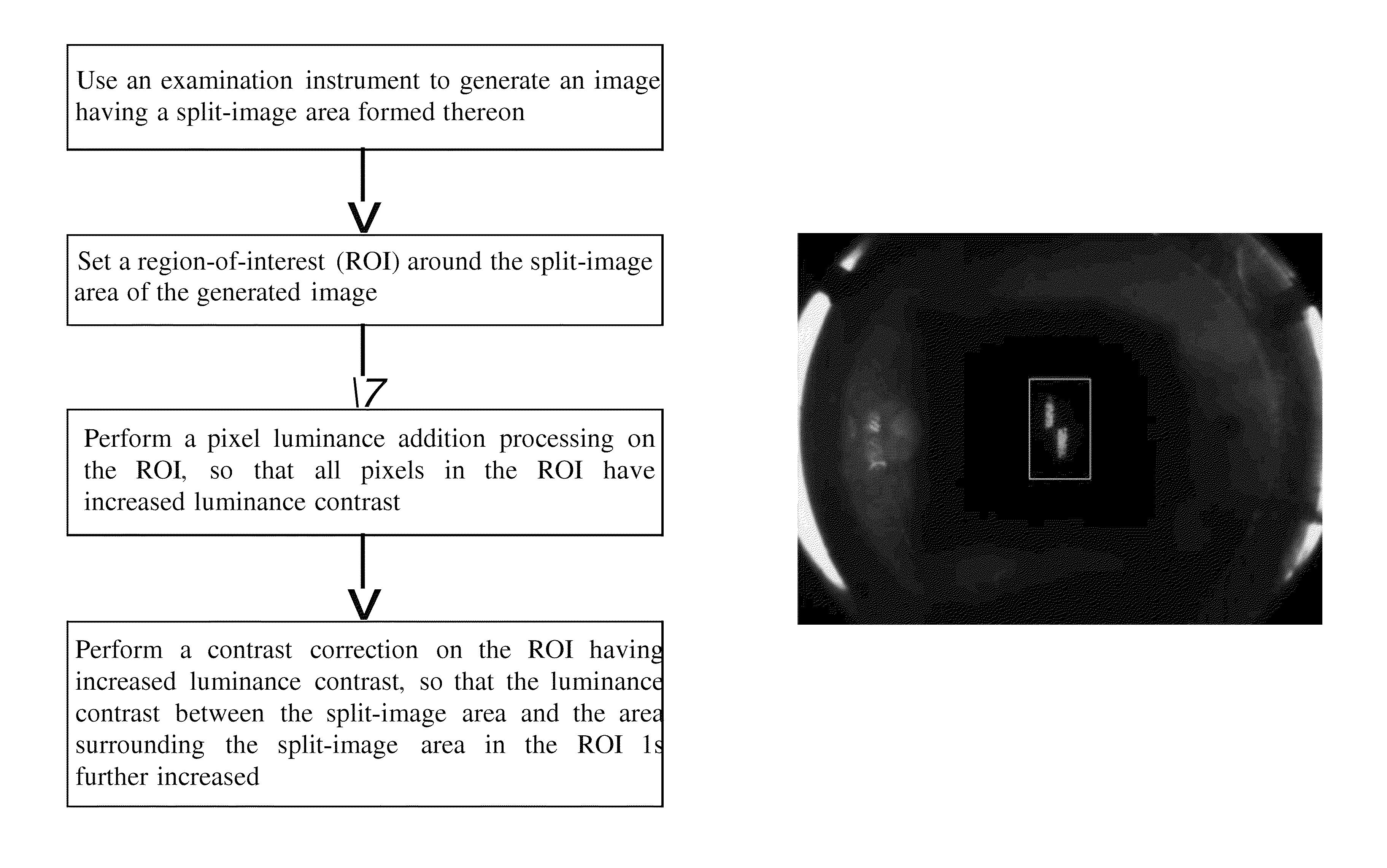
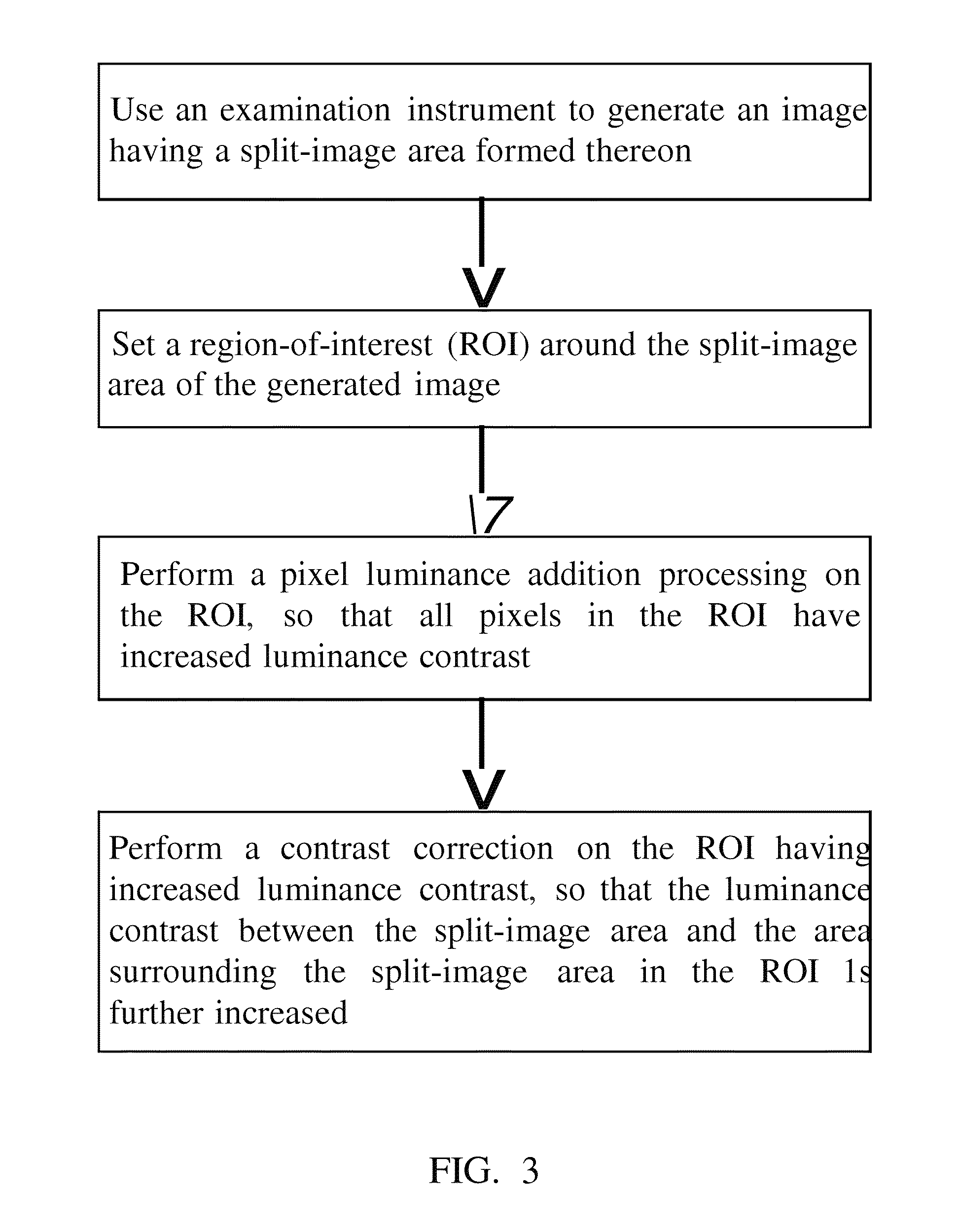
[0019]Please refer to FIG. 3, which is a flowchart of an image-recognition assisting method according to a preferred embodiment of the present invention. As shown, the image-recognition assisting method of present invention includes the following steps:[0020](a) Using an examination instrument to generate an image having a split-image area formed thereon;[0021](b) Setting a region-of-interest (ROI) around the split-image area of the generated image;[0022](c) Performing a pixel luminance addition processing on the ROI, so that all pixels in the ROI have increased luminance contrast; and[0023](d) Performing a contrast correction on the ROI having increased luminance contrast, so that the luminance contrast between the split-image area and the area surrounding the split-image area in the ROI is further increased.

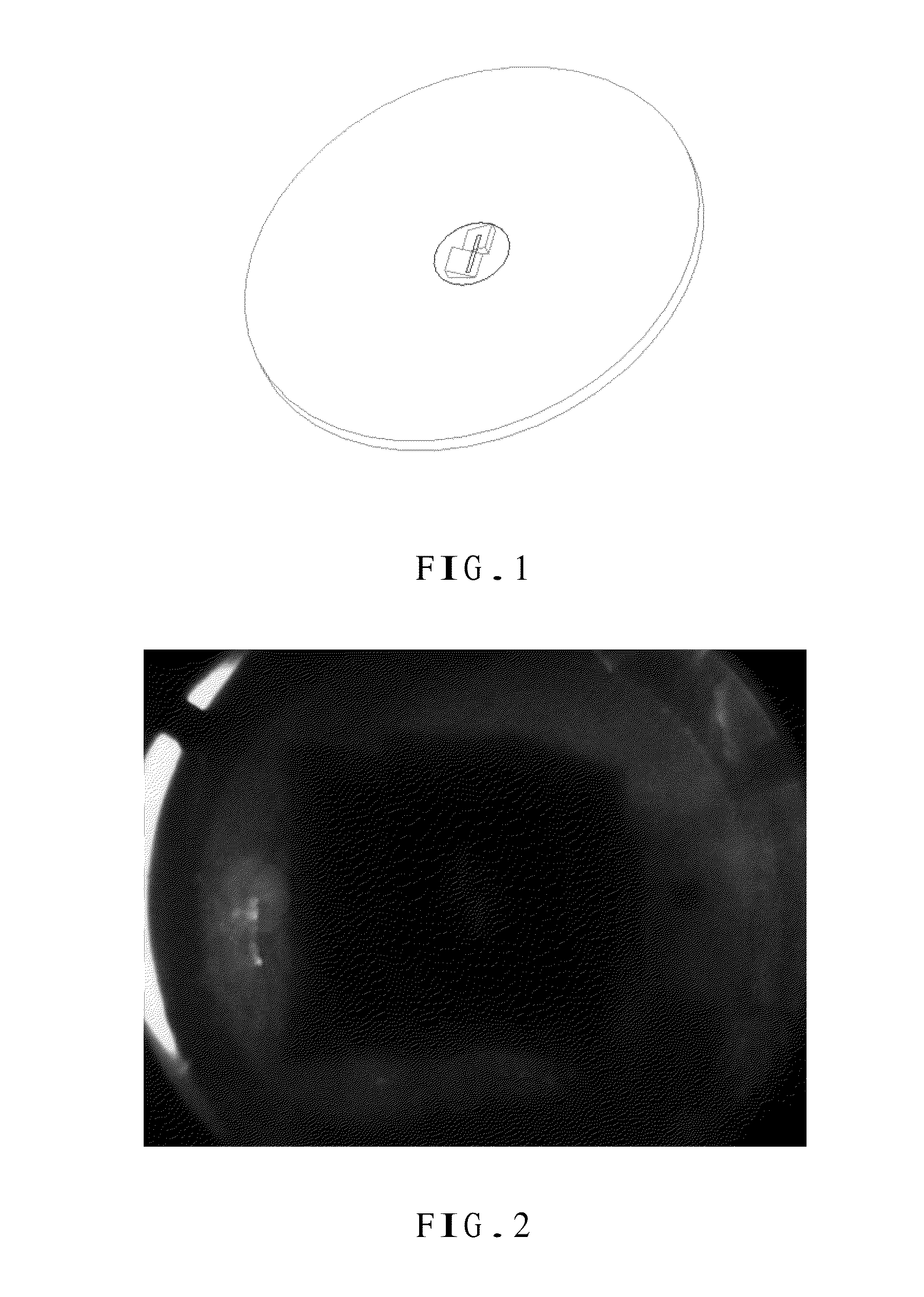
[0024]Please refer to FIG. 2. The examinat...


PUM


Abstract

An image-recognition assisting method includes the steps of using an examination instrument to generate an image having a split-image area formed thereon; setting a region-of-interest (ROI) around the split-image area of the generated image; performing a pixel luminance addition processing on the ROI, so that all pixels in the ROI have increased luminance contrast; and performing a contrast correction on the ROI having increased luminance contrast, so that the luminance contrast between the split-image area and the area surrounding the split-image area in the ROI is further increased. The image-recognition assisting method optimizes the image generated by the conventional ophthalmic examination instrument, such as a fundus camera, to increase the sharpness and the luminance contrast of the image output by the fundus camera, so that an examiner can easily recognize two offset rectangular image parts in the split-image area and align them with each other to focus the examination instrument.

Description

FIELD OF THE INVENTION[0001]The present invention relates to an image recognition method applied to optical focusing of examination instruments, and more particularly to an image-recognition assisting method for optimizing the sharpness and luminance contrast of a split image formed by a split-image focusing screen on, for example, a fundus image captured by an ophthalmic examination instrument, so that an examiner can easily recognize the optimized split image to focus the fundus image for outputting.BACKGROUND OF THE INVENTION[0002]Most of the conventional eye-fundus cameras use a split-image focusing screen to assist in focusing thereof. Please refer to FIG. 1. The split-image focusing screen utilizes two prisms and a slit to form a split image having an upper and a lower rectangular image part on an image sensor, such as a charge coupled device (CCD) sensor. When an eye-fundus camera is not focused, the two rectangular image parts are vertically offset from each other, i.e. they...

Claims


Application Information

Patent Timeline
Patent Type & Authority Patents(United States)
IPC IPC(8): G06K9/00G06V10/25
CPCG06K9/3233G06T2207/30041G06T7/0012G06K9/00G06T5/008G06V10/25
Inventor LIN, CHUN NANCHUANG, CHUNG PINGTSAI, CHE LIANG
Owner CRYSTALVUE MEDICAL
Why Eureka
Eureka Blog
Learn More