
Control apparatus for vehicular power transmitting apparatus

a control apparatus and transmission device technology, applied in fluid gearings, instruments, gearings, etc., can solve the problems of increasing development man-hours and complex hydrostatic control circuits, and achieve the effect of complex structure and failure to detect performan

Active Publication Date: 2014-07-15
TOYOTA JIDOSHA KK
View PDF31 Cites 3 Cited by
  • Summary
  • Abstract
  • Description
  • Claims
  • Application Information

AI Technical Summary

Benefits of technology

[0009]With the control apparatus for a vehicular power transmitting apparatus according to the aspect described above, the failure state of a part is detected based on the operating state of the running clutch and the operating state of the lockup clutch. Therefore, the failure state of a part can be detected without providing a hydraulic sensor and an oil pressure switch or the like for detecting a failure. That is, failure detecting performance can be ensured without increasing the number of parts and making the structure more complex.

Problems solved by technology

Therefore, with the structure described in Japanese Patent No. 4069054, an oil pressure switch and a hydraulic sensor for detecting a failure of the linear solenoid valve are necessary, and as a result, the hydraulic control circuit becomes complex.
In addition, a system is necessary for successively detecting failures in the oil pressure switch and hydraulic sensor themselves, which ends up increasing development man-hours.

Method used


Image

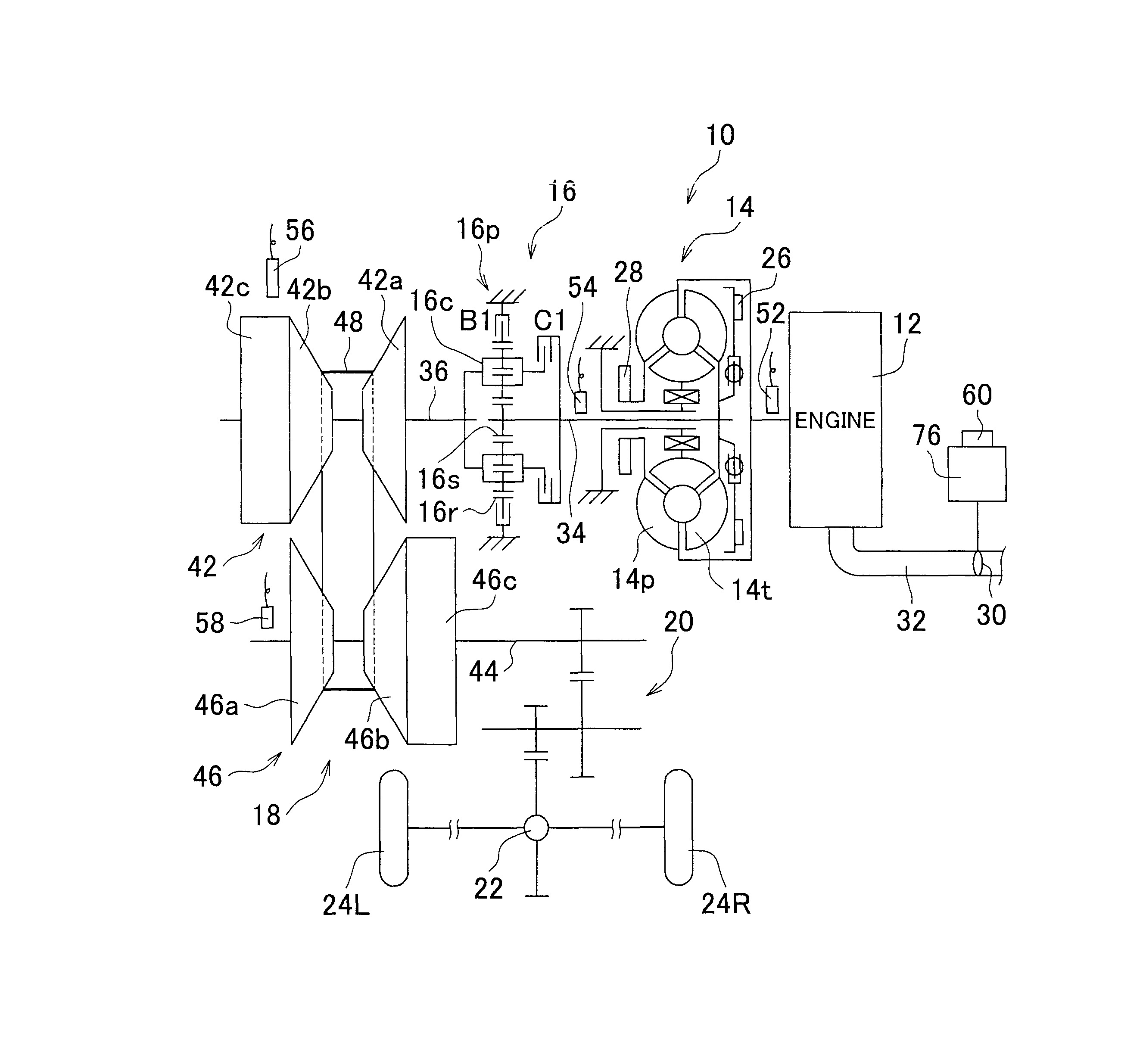
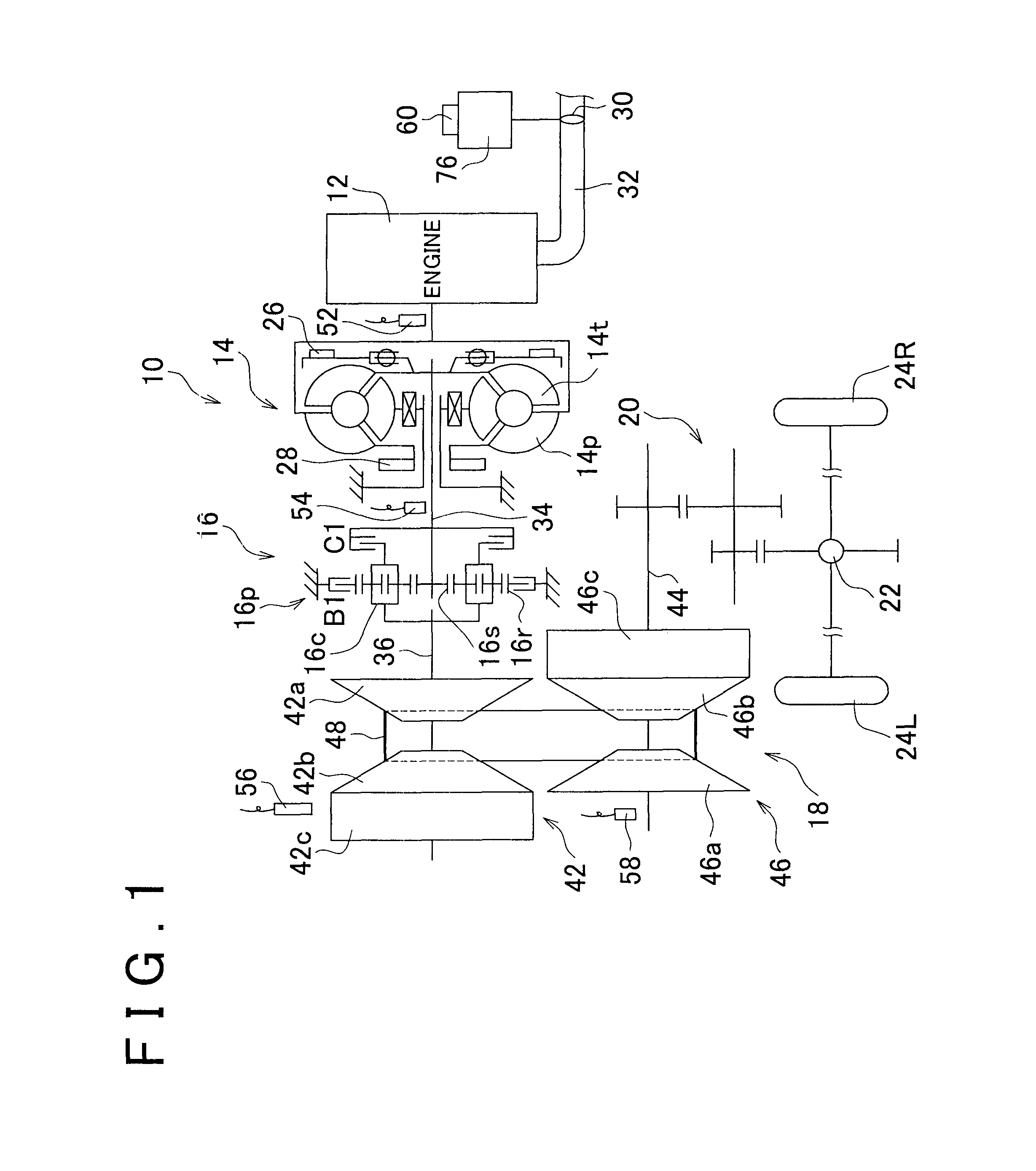
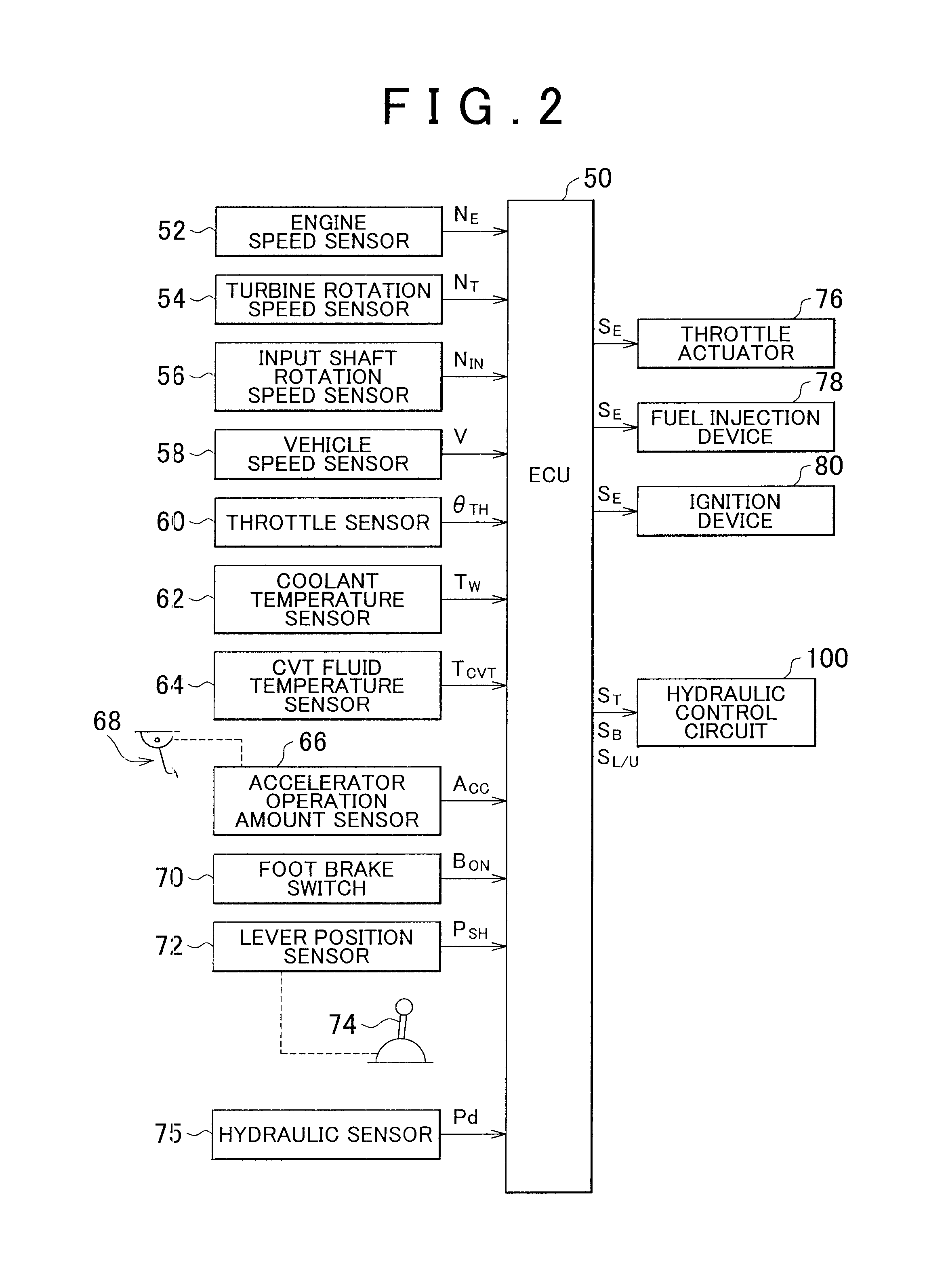
  • Control apparatus for vehicular power transmitting apparatus
  • Control apparatus for vehicular power transmitting apparatus
  • Control apparatus for vehicular power transmitting apparatus

Examples


Embodiment Construction

[0023]In an example embodiment of the invention, an on failure of the first solenoid valve, the second solenoid valve, and the linear solenoid valve corresponds to a failure in which hydraulic pressure is constantly output from each of those electromagnetic valves. Also, an off failure of the first solenoid valve, the second solenoid valve, and the linear solenoid valve corresponds to a failure in which hydraulic pressure is not output despite a command being output to output hydraulic pressure from each of those electromagnetic valves.

[0024]Also, in the example embodiments of the invention, the transmission corresponds to a belt-type continuously variable transmission. Therefore, the direction in which the vehicle travels can be appropriately switched by the running clutch.

[0025]Hereinafter, example embodiments of the invention will be described in detail with reference to the accompanying drawings. Incidentally, the drawings described in the example embodiments below have been sim...


PUM


Abstract

A control apparatus for a vehicular power transmitting apparatus includes a first valve that controls the supply of hydraulic fluid to a running clutch in connection with the switching of the operating state of a first solenoid valve; a second valve that controls the supply of hydraulic fluid to a lockup clutch in connection with the switching of the operating state of a second solenoid valve; and a linear solenoid valve that selectively controls the apply force of the running clutch and the lockup clutch according to the supply of control pressure to the first valve and the second valve. The control apparatus detects a failure state of a part related to the operation of the power transmitting apparatus by the operating state of the running clutch and the operating state of the lockup clutch.

Description

INCORPORATION BY REFERENCE[0001]The disclosure of Japanese Patent Application No. 2009-237764 filed on Oct. 14, 2009 including the specification, drawings and abstract is incorporated herein by reference in its entirety.BACKGROUND OF THE INVENTION[0002]1. Field of the Invention[0003]The invention relates to a control apparatus for a vehicular power transmitting apparatus, and more particularly, to failure detection in that vehicular power transmitting apparatus.[0004]2. Description of the Related Art[0005]Clutches and brakes provided in a vehicular power transmitting apparatus are formed of hydraulic actuators driven by hydraulic pressure, and are controlled appropriately by a hydraulic control circuit. In this hydraulic control circuit there are a plurality of individual linear solenoid valves that are able to be electrically controlled. The apply force of the clutches and brakes is optimally controlled based on control pressure output from these linear solenoid valves. Incidentall...

Claims


Application Information

Patent Timeline
Patent Type & Authority Patents(United States)
IPC IPC(8): G06F19/00G07C5/00G06F7/00G06F11/30G01M17/00
CPCY10T477/621F16H2061/1208F16H61/12F16D2500/5108F16H61/143Y10T477/6203F16H61/20F16H2061/1224Y10T477/619Y10T477/60Y10T477/6197F16D48/066F16D2500/1026F16H2061/1264F16D2500/3024F16D48/062F16D2500/10412F16D2500/1068F16D2500/1088F16D2500/3067F16D2500/30803F16D2500/30816F16D2500/3108F16D2500/31433F16D2500/3144F16D2500/31466F16D2500/5102F16D2500/5114F16D2500/70217F16D2500/7027F16D2500/70276F16D2500/70282F16D2500/70462
Inventor IRAHA, TAIRAHATTORI, KUNIO
Owner TOYOTA JIDOSHA KK
Learn More