Electronic control unit
a control unit and electronic technology, applied in the direction of electrical control, power supply testing, instruments, etc., can solve the problems of fusion cutting of a wiring pattern, serious failure, etc., and achieve the effect of short time and high accuracy of failure diagnosis
- Summary
- Abstract
- Description
- Claims
- Application Information
AI Technical Summary
Benefits of technology
Problems solved by technology
Method used
Image
Examples
first embodiment
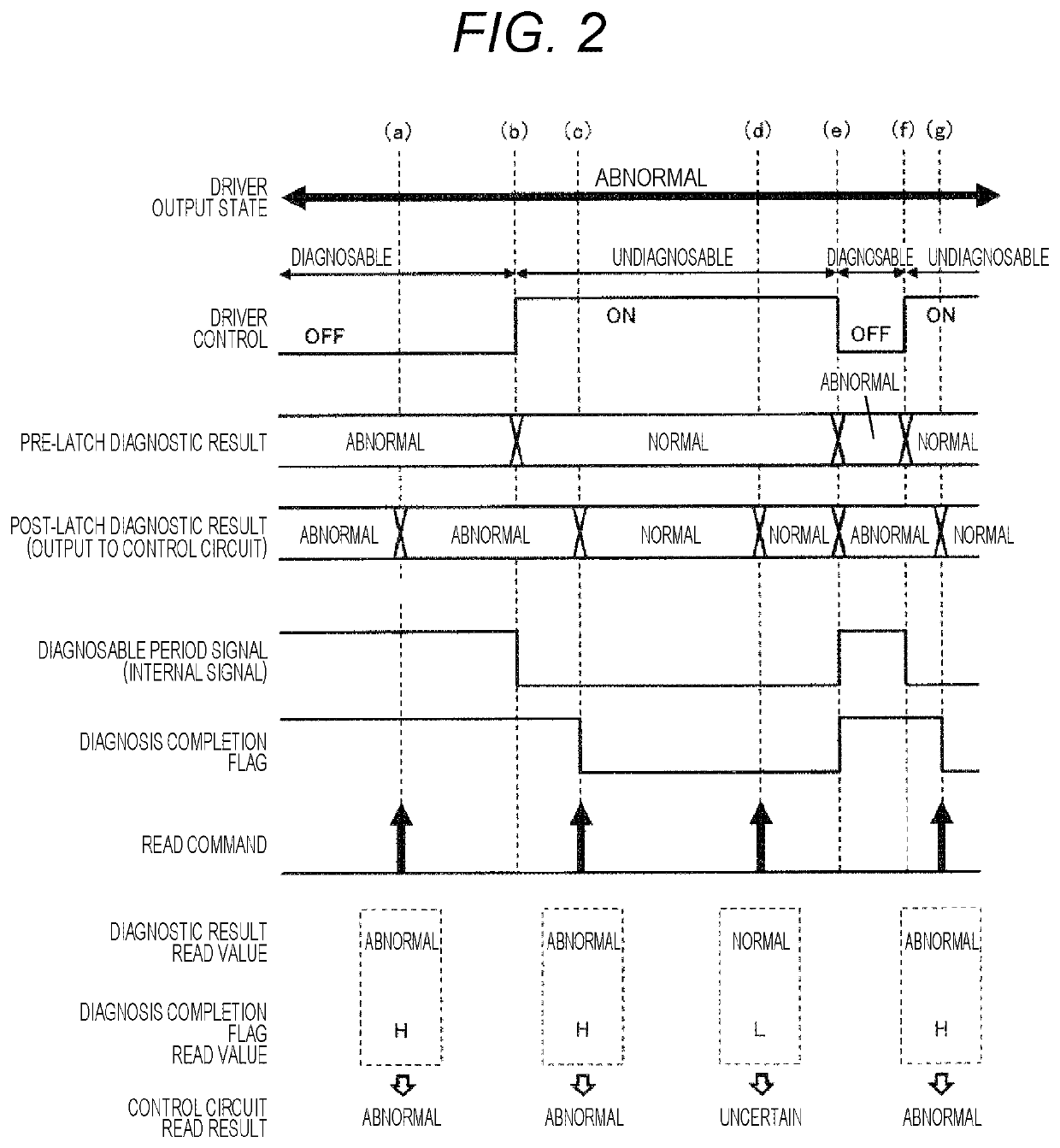
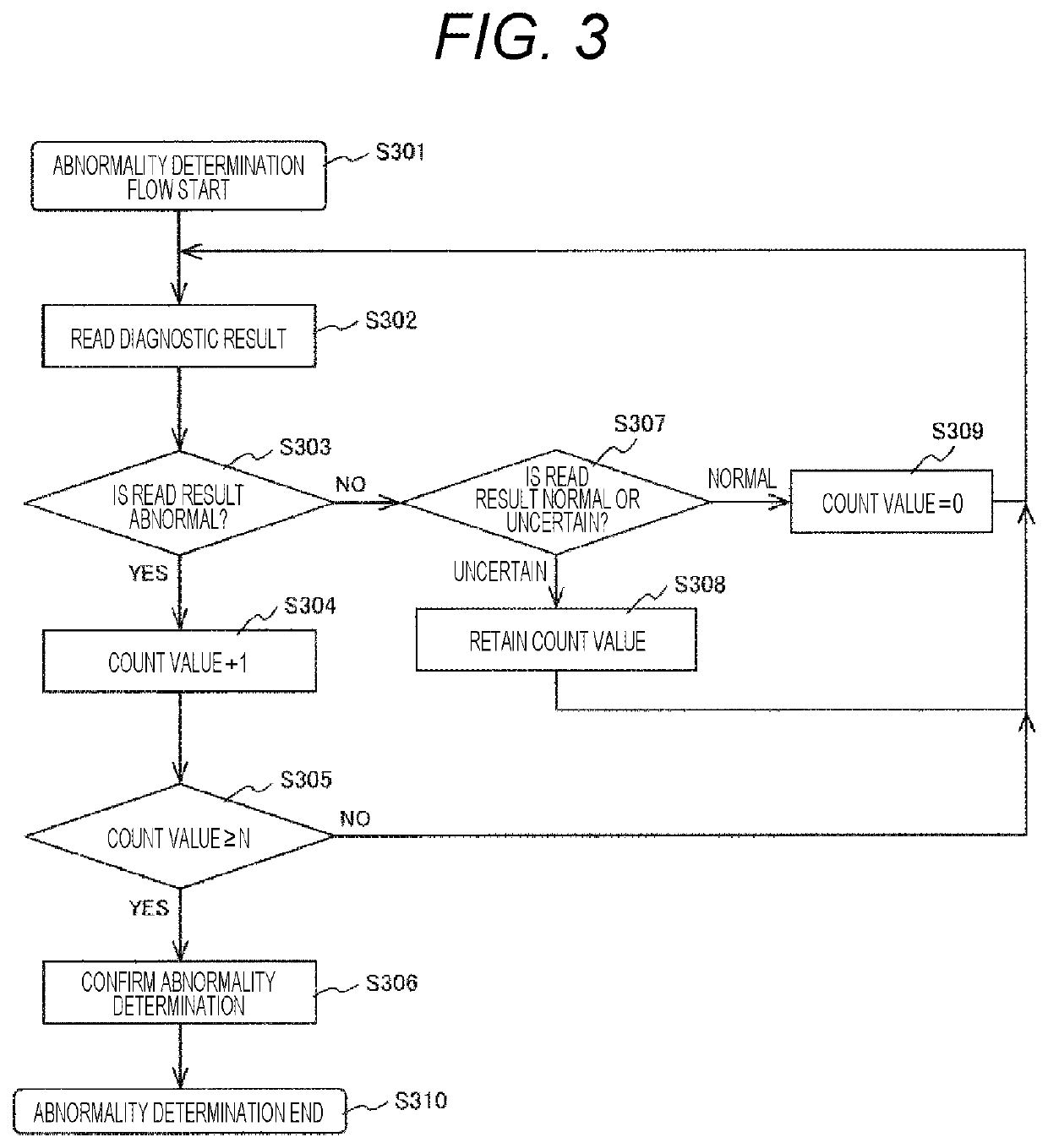
[0027]A load drive device (electronic control unit) according to a first embodiment of the present invention will be described with reference to FIGS. 1 to 5.
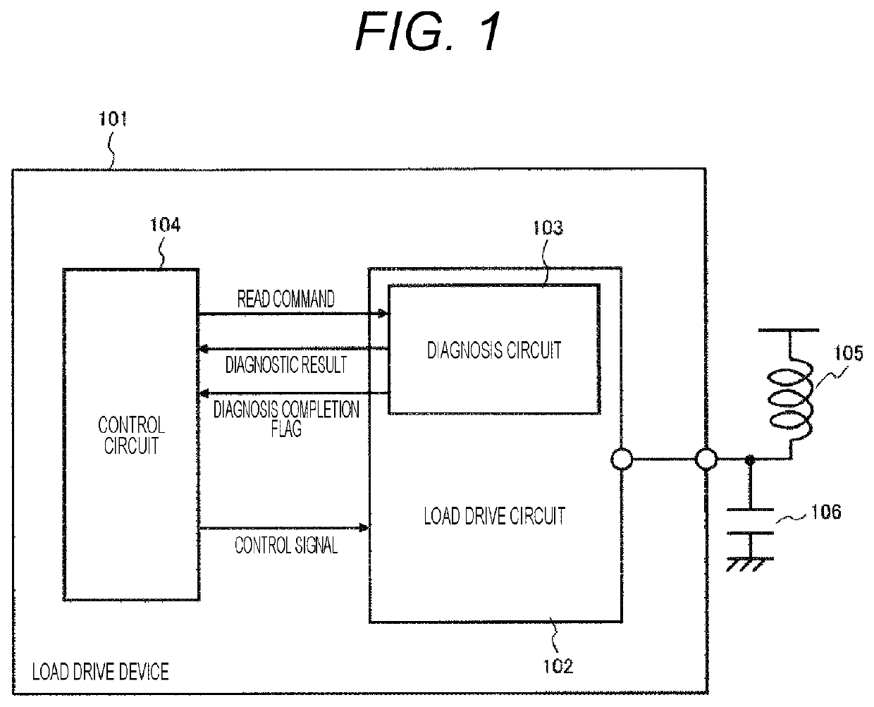
[0028]FIG. 1 illustrates a circuit configuration of the load drive device (electronic control unit) of the present embodiment. A load drive device 101 of the present embodiment includes a load drive circuit 102 and a control circuit 104 that controls the load drive circuit 102. The load drive circuit 102 includes a diagnosis circuit 103 that diagnoses an output state of the load drive device 101 (load drive circuit 102) and outputs a diagnostic result to the control circuit 104.
[0029]The load drive circuit 102 drives a load based on a control signal output from the control circuit 104. FIG. 1 illustrates an example of an inductive load including a winding wire (coil) 105 and a capacitive element (capacitor) 106. The diagnosis circuit 103 diagnoses the output state of the load drive device 101 by monitoring an output voltage or ...
second embodiment
[0078]A load drive device (electronic control unit) according to a second embodiment of the present invention will be described with reference to FIG. 6. Since a circuit configuration diagram in the present embodiment is common to FIG. 1 in the first embodiment, the redundant description will be omitted.
[0079]FIG. 6 is a timing chart illustrating an operation of the load drive circuit 102 in the present embodiment.
[0080]While there is the diagnosable period signal and the operation in which the diagnosis completion flag is High in the diagnosable period and is Low in the undiagnosable period in the first embodiment, there is no diagnosable period signal and the diagnosis completion flag has the same operation as the diagnosable period signal in the first embodiment in the present embodiment.
[0081]That is, the diagnosis completion flag is not latched (the state is not maintained) even after becoming High, and falls immediately at the time of entering the undiagnosable period. In this...
third embodiment
[0085]A load drive device (electronic control unit) according to a third embodiment of the present invention will be described with reference to FIG. 7. FIG. 7 is a circuit configuration diagram of the load drive device (electronic control unit) in the present embodiment.
[0086]In the present embodiment, configurations of a driver IC 702 and a microcontroller 703 are different from those in the first embodiment. Since the other configurations are the same as those in the first embodiment, the redundant description will be omitted.
[0087]In a load drive device (electronic control unit) 701 of the present embodiment, the control circuit 104 is replaced with the microcontroller 703 and the load drive circuit 102 is replaced with the driver IC 702 with respect to the configuration of the first embodiment. Communication between the microcontroller 703 and the driver IC 702 is serial communication.
[0088]In the present embodiment, all the control signal, the read command, the diagnostic resu...
PUM
| Property | Measurement | Unit |
|---|---|---|
| response time | aaaaa | aaaaa |
| voltage | aaaaa | aaaaa |
| current | aaaaa | aaaaa |
Abstract
Description
Claims
Application Information
 - R&D
- Intellectual Property
- Life Sciences
- Materials
- Tech Scout
- Unparalleled Data Quality
- Higher Quality Content
- 60% Fewer Hallucinations
Browse by: Latest US Patents, China's latest patents, Technical Efficacy Thesaurus, Application Domain, Technology Topic, Popular Technical Reports.
© 2025 PatSnap. All rights reserved.Legal|Privacy policy|Modern Slavery Act Transparency Statement|Sitemap|About US| Contact US: help@patsnap.com


