
Systems and methods for setting correspondence between pieces of equipment, locations and elements of a lockout procedure checklist

Active Publication Date: 2021-11-11
BORDELEAU ERIC
View PDF0 Cites 0 Cited by
  • Summary
  • Abstract
  • Description
  • Claims
  • Application Information

AI Technical Summary

Benefits of technology

The patent text describes a system and method for validating the correspondence between points, steps, or other information of a security procedure and either a piece of equipment or a location. The system includes a procedure checklist printed over a markable support, which contains a first element and a second element with different graphical assemblies. Marking tools attached at the location of the procedure checklist generate markings on the support that match the graphical assemblies. The markings are compared with the graphical assemblies to validate the procedure. The technical effect of this system is to provide a more efficient and effective means of ensuring the proper execution of a security procedure.

Problems solved by technology

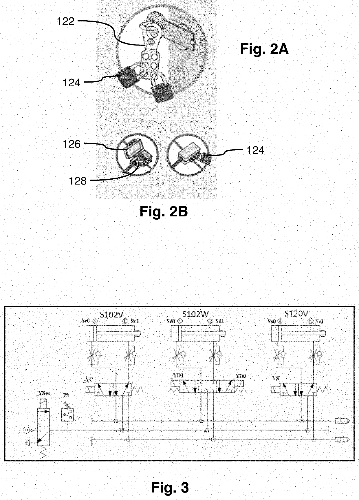
Once a potentially dangerous piece of equipment is turned off, for example, the switch for the equipment may be locked out (e.g., using a hasp having multiple apertures) using multiple padlocks.
Difficulties encountered with lockout procedure include difficulty for the operator to efficiently and with a very low failure-level to validate correspondence between the pieces of equipment and / or locations listed on the procedure checklist and the physical pieces of equipment and / or locations in the workplace, with each failure in successfully performing correspondence resulting in increases risks for the operator.
In practice, if a process of the procedure checklist is ill-performed, for example over a circuit cutting point, the associated dangerous energy source remains to provide risks in the assumedly secured zone.
The same risks result also from an ill-determination of the location of the secured zone.
However, these solutions have important drawbacks, some regarding the costs to put in place these solutions and / or to maintain the solutions, some of them with the difficulty or the extra work associated with using these solutions.
The latter in practice results frequently in a portion of the operators failing to follow the securing procedure, and thus failing in securing the zone where they are working.
However, this kind of solution is costly to install.
Furthermore, the additional energy source cutting means, as any piece of equipment, feature risks of future failures that may negatively influence the production capacity of the workplace in the future, that may increase the difficulty to identify the nature of failures and that may increase costs and maintenance requirements.
Finally, an increase in the number of pieces of equipment to be under lockout also increases the chances of any one of these pieces of equipment being forgotten at the time to remove the lockout from the pieces of equipment, which would automatically result in delays in production on the workplace.
Therefore, when about to work in the secured zone, an operator checks the state of the light signal(s), and if not depicting a safe condition, the operator will have to leave the to-be-secured zone to reach the piece of equipment allowing to control the dangerous energy source before returning to the secured zone, what may sum up to a lot of displacement.
Furthermore, this solution is costly to install, requiring once again more complex electric circuits increasing with the distance between the piece of equipment used to control the energy source and the zone to be secured.
In the particular case when two operators have to work in the same secured zone, based on distinct lockout protocols, the process becomes even more complex.
For example, it is complex for the second operator to determine the specific steps of the lockout procedure to perform versus already performed by the first operator.
Thus, risks remain with the present solution nowadays available.
Therefore, that solution provides numerous drawbacks, including that in some cases the selected solution does not match the daily routine and requirements of the operators.
For example, such a solution may result when a machine is under maintenance between shifts resulting in confusion in the states of lockout or not at the beginning of the following shift.
Such installation is costly to install since these controls, must always be free of interlock, e.g., with industrial automates and emergency stop controls.
This technique does not allow to eliminate the risks of errors since, during maintenance stops, all of the machines are stopped, which renders lockout processes upstream very difficult to test.
An outcome of this is a potentially dangerous confusion resulting from multiple lockouts at different points along the energy line(s) feeding a machine.
In order to mitigate the risks of confusion, some companies require to perform a starting test over a machine before performing a lockout process, which results once again in costs and delays.
Thus, all of these solutions have drawbacks having variable results ranging from increased costs, decreased productivity, increased sources of confusion, a decrease of the engagement of the operators in following the procedures and increased risks, which is opposed to the object of these procedures to eliminate or at least to mitigate these risks.

Method used


Image

  • Systems and methods for setting correspondence between pieces of equipment, locations and elements of a lockout procedure checklist
  • Systems and methods for setting correspondence between pieces of equipment, locations and elements of a lockout procedure checklist
  • Systems and methods for setting correspondence between pieces of equipment, locations and elements of a lockout procedure checklist

Examples


Embodiment Construction

[0070]Before turning to the description and the figures, which illustrate the exemplary embodiments in detail, it should be understood that the application is not limited to the details or methodology set forth in the description or illustrated in the figures. It should also be understood that the terminology is for the purpose of description only and should not be regarded as limiting.

[0071]First, to understand the present description, one must have a broad grasp of a lockout (securing) procedure. A securing procedure or, failing that, “any other method that ensures equivalent safety” must be followed for work in a machine's danger zone. The types of work in question are installing, servicing, maintaining, adjusting, cleaning, inspecting, unjamming, setting up, and decommissioning. The goal of these methods is to prevent any untimely release of energy that could cause an accident in the course of the work. The steps involved in a securing procedure are: 1—deactivation and complete ...


PUM


Abstract

Systems and methods for setting correspondence between pieces of equipment, locations and elements of a lockout procedure checklist comprising a procedure checklist and marking tools. The procedure checklist is printed over a markable support and comprises elements printed thereon each comprising a unique graphical assemblage. Marking tools, provided at locations to perform securing operations on pieces of equipment, are adapted to generate markings on the support matching the graphical assemblages. The operator following each of the elements of the procedure uses the marking tools at the locations to generate markings on the support, and thereby completion of the procedure may be validated by comparing the markings generated on the support with the graphical assemblages thereon. Procedure allows to validate that operations are performed only on appropriate pieces of equipment and location, and that all steps are performed.

Description

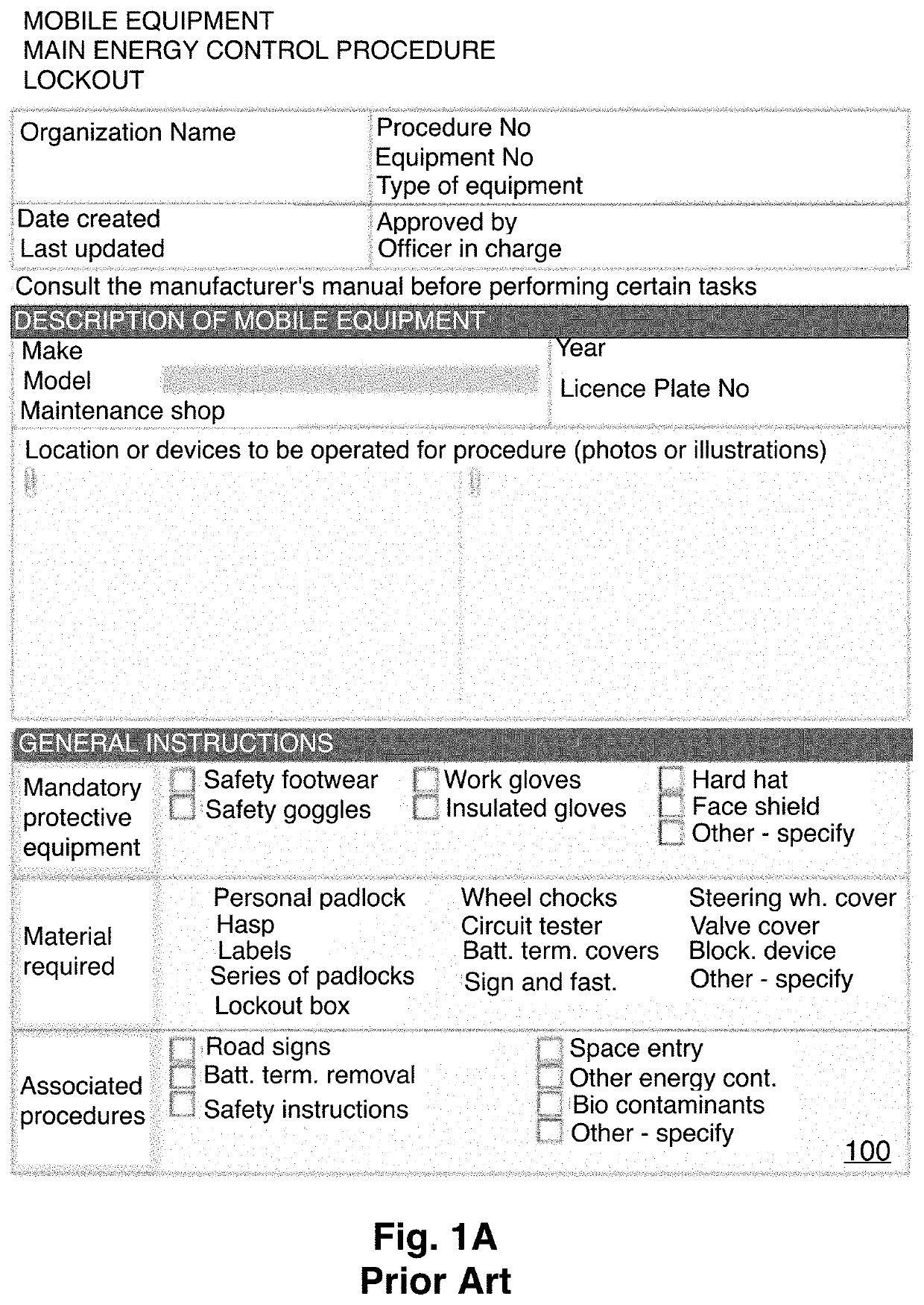
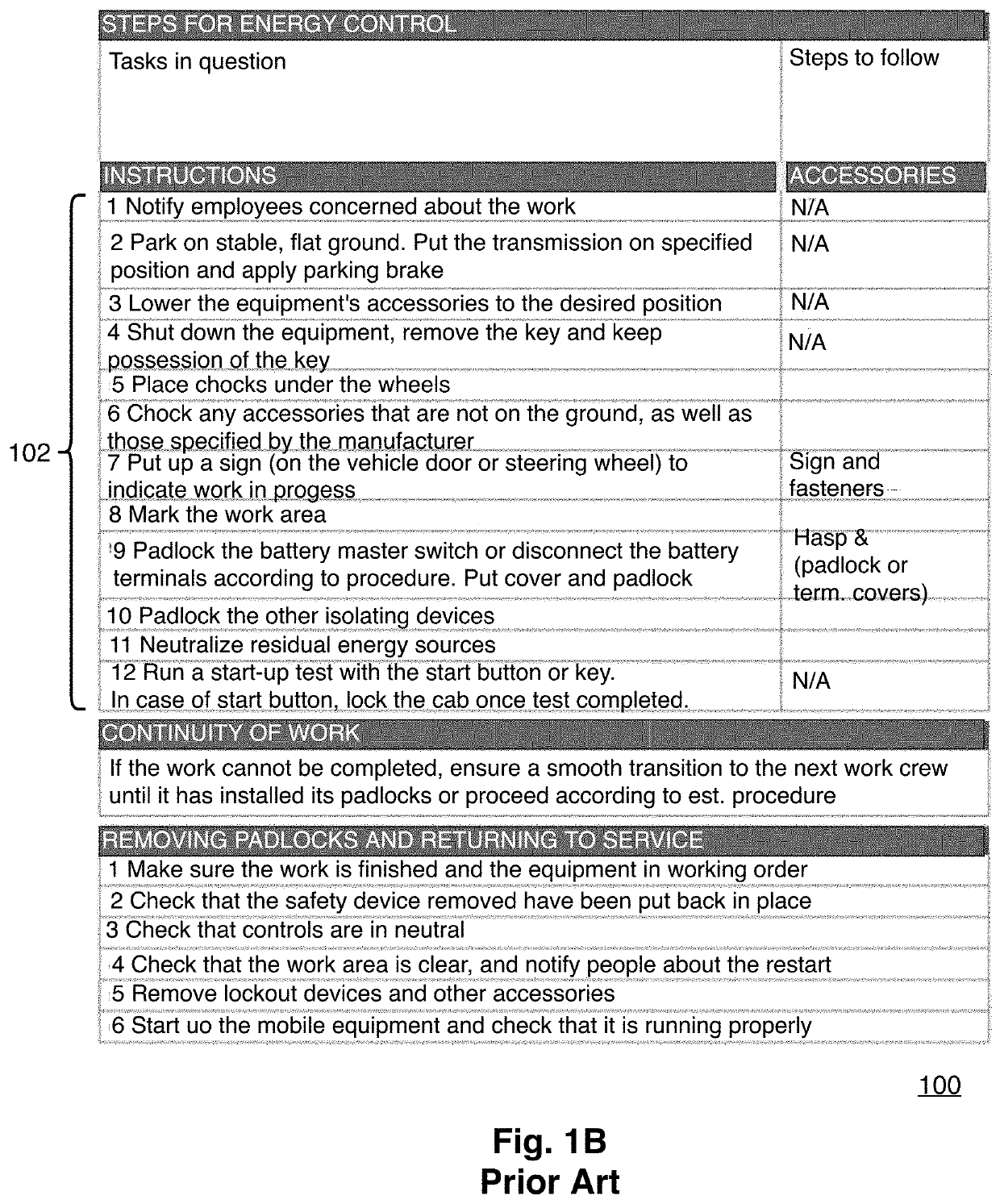
CROSS-REFERENCE TO RELATED APPLICATION[0001]This application claims priority from U.S. provisional patent application 63 / 021,714 filed May 8, 2020, the specification of which is hereby incorporated herein by reference in its entirety.BACKGROUND(a) Field[0002]The subject matter disclosed generally relates to the field of lockout, aka securing, procedures and systems. The present disclosure relates more specifically to the use of visual technology to improve securing procedures and systems.(b) Related Prior Art[0003]In some applications, certain areas or equipment call for multiple processes to occur before granting access or restricting access from zones or equipment. These multiple steps are often intended to help ensure that a safety process is properly completed. Lockout or securing systems are used to support such processes.[0004]Once a potentially dangerous piece of equipment is turned off, for example, the switch for the equipment may be locked out (e.g., using a hasp having mu...

Claims


Application Information

Patent Timeline
IPC IPC(8): G06Q90/00G06F3/12G06K1/08G06K19/04
CPCG06Q90/00G06K19/04G06K1/08G06F3/12G06Q10/0633G06Q10/20G06Q10/06398B26F1/36
Inventor BORDELEAU, ERIC
Owner BORDELEAU ERIC
Learn More