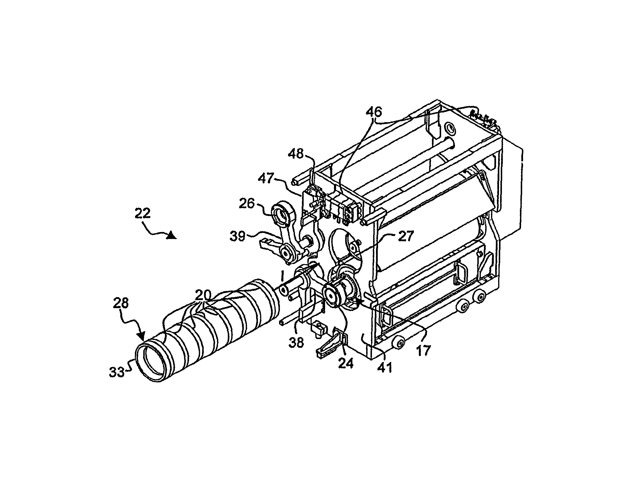
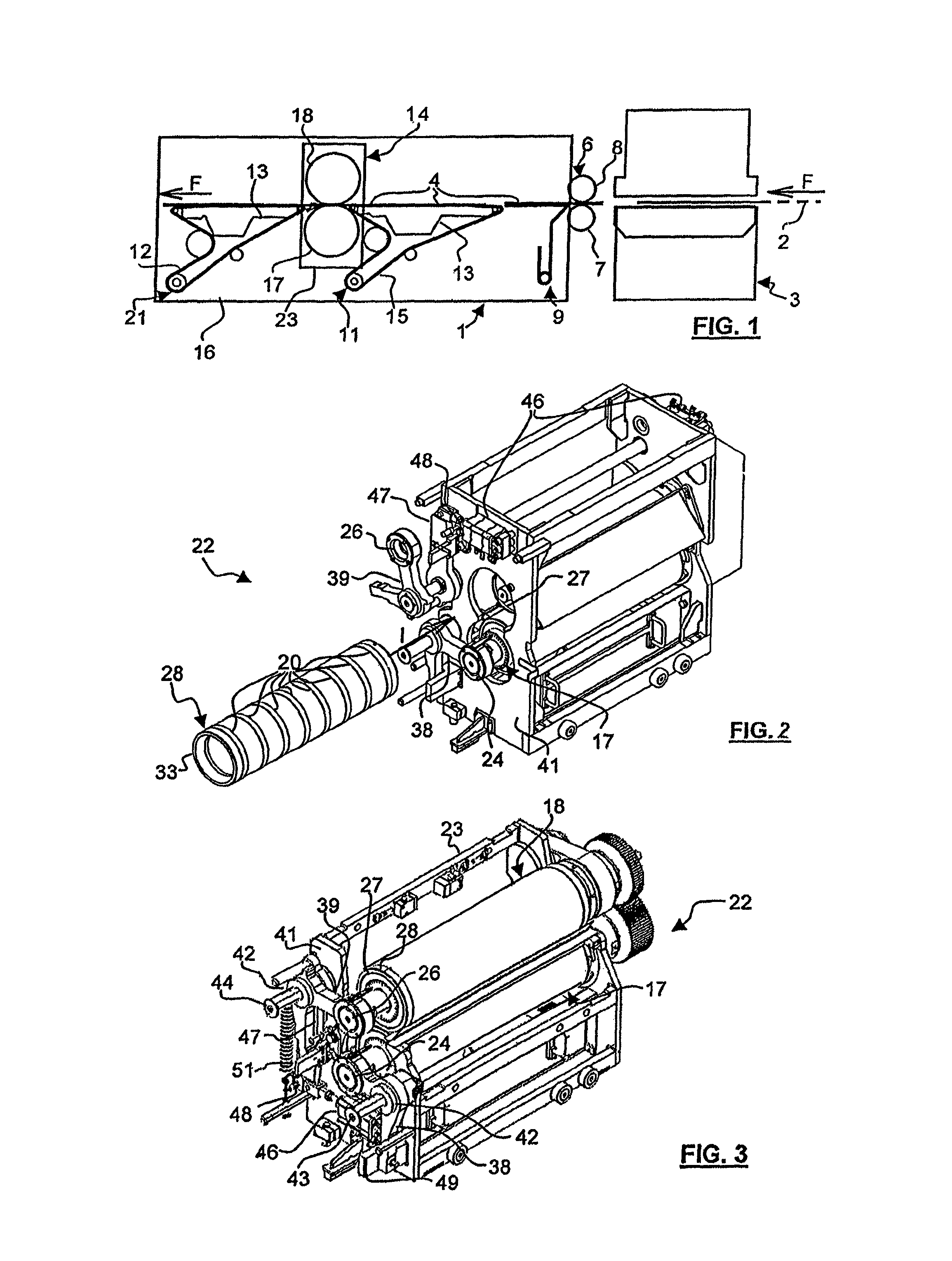
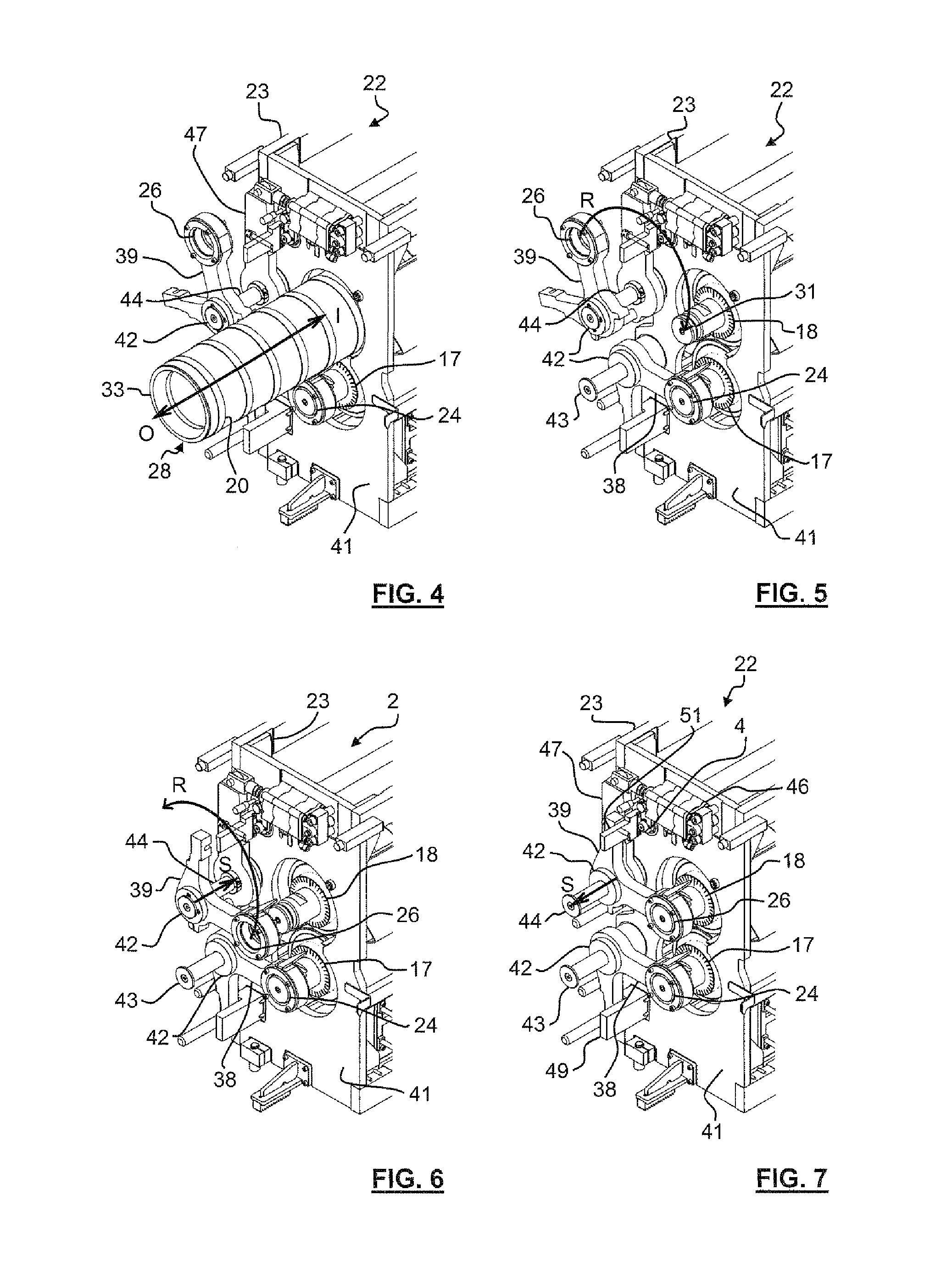
Waste stripping unit with simplified tool change for a packaging production machine

a production machine and tool change technology, applied in the field of waste stripping units, can solve the problems of frequent cylinder handling operations, inability to quickly change the cylinder, and long and tedious operations involved in changing the cylinder, so as to reduce the risk of needle introduction errors, facilitate access, and facilitate mounting and dismounting.

Active Publication Date: 2014-07-22
BOBST MEX SA
View PDF40 Cites 13 Cited by
  • Summary
  • Abstract
  • Description
  • Claims
  • Application Information

AI Technical Summary

Benefits of technology

[0015]A main objective of the present invention is to develop a waste stripping unit positioned downstream of a cutting unit for a packaging production machine. A second objective is to produce a waste stripping unit that allows the stripping tool or tools to be prepared outside the machine. A third objective is to simplify and facilitate any change of one or more stripping tools. Yet a fourth objective is to obtain stripping of the waste that avoids the problems of the state of the art. Yet another objective is to provide a packaging production machine with a waste stripping unit integrated after an upstream cutting unit and that offers a wide flexibility of use.
[0017]In other words, with the replacement of a removable sleeve bearing a series of needles or at least one strip of flexible material with another removal sleeve bearing another series of needles or at least one other strip of flexible material, the job change is performed in a very short time. A bottom sleeve with a bottom mandrel form the bottom tool and / or a top sleeve with a top mandrel form the top tool. The two tools are inexpensive and at most require only two sleeves. As an example, the weight of a removable sleeve is less than 18 kg, this weight having to be compared with that of a complete tool.
[0024]With one or two sleeves and the waste stripping cassette, access, mounting and dismounting are facilitated for the operator responsible for setting and maintaining the unit and the machine. With a more ergonomic stripping unit, the risk of error in introducing the needles is greatly reduced, which consequently results in a reduction in the number of blanks or boxes that fail to conform or do not have optimum quality.

Problems solved by technology

However, the operations involved in changing stripping cylinders prove to be lengthy and tedious.
Because of the fairly heavy weight, a change of cylinder cannot be performed very quickly.
The frequent cylinder handling operations thus prove lengthy and tedious.
The cylinder spiked with needles represents an injury danger to the operator.

Method used


Image

  • Waste stripping unit with simplified tool change for a packaging production machine
  • Waste stripping unit with simplified tool change for a packaging production machine
  • Waste stripping unit with simplified tool change for a packaging production machine

Examples


Embodiment Construction

[0031]As FIG. 1 illustrates, a packaging production machine (1) processes a substrate or a material in a continuous strip (2), which is in this case flat cardboard. The machine (1) comprises a transformation unit, for example a diecutting platen press (3). Upstream of the press (3), the machine (1) may have units such as printing units, means for checking quality and register, embossing units, etc. (not represented).

[0032]The strip (2) enters into the press (3) from its upstream transverse side. The press (3) cuts the strip (2) and delivers the substrate in the form of blanks (4), made of flat cardboard. The blanks (4) leave the press (3) by its downstream transverse side. The direction of progress or of advance (arrows F) of the strip (2) and of the blanks (4) in the longitudinal direction indicates the upstream direction and the downstream direction.

[0033]The machine (1) comprises a drive arrangement (6), which is arranged downstream of the press (3). This arrangement (6) firstly ...


PUM

PropertyMeasurementUnit
weightaaaaaaaaaa
weightaaaaaaaaaa
flexibleaaaaaaaaaa

Abstract

A waste stripping unit in a packaging production machine (1), positioned downstream of a cutting unit (3) for cutting one or more flat substrates (4). The stripping unit includes a frame (16) supporting two rotary tools cooperating with one another (17, 18). At least one of the two tools (17, 18) is formed with a mandrel (27) and a removable sleeve (28), and the sleeve can be inserted on, fixed to and driven in rotation by the mandrel (27). One tool has protruding needles for the stripping and the other tool has a flexible strip cooperating with the needles.

Description

CROSS-REFERENCE TO RELATED APPLICATIONS[0001]The present application is a 35 U.S.C. §§371 national phase conversion of PCT / EP2010 / 002922, filed May 12, 2010, which claims priority of European Application No. 09006437.9, filed May 13, 2009, the contents of which are incorporated by reference herein. The PCT International Application was published in the French language.[0002]The present invention relates to a waste stripping unit for waste obtained by cutting a flat substrate. The invention also relates to a waste stripping unit that facilitates any stripping tool change. The invention also relates to a packaging production machine comprising, in order and in succession, a cutting unit and a waste stripping unit.[0003]A packaging production machine is intended for the production of boxes, which will form packaging, after folding and gluing. In this machine, an initial flat substrate, such as a continuous strip of cardboard, is unwound and printed by a print unit, itself consisting of...

Claims


Application Information

Patent Timeline
Patent Type & Authority Patents(United States)
IPC IPC(8): B26D7/20B23D25/12B26D7/06B31B50/20
CPCY10T83/4841Y10T83/207B26D7/00Y10T83/2098B26D7/1836Y10T83/2096Y10T83/9466B26D7/18B26D5/00B65H35/08
Inventor COMPAGNONE, GIOVANNICORMINBOEUF, GLENN
Owner BOBST MEX SA
Why Eureka
Try Eureka