
Waste stripping unit with simplified tool adjustment in a packaging production machine

a production machine and tool adjustment technology, applied in the field can solve the problems of long operation time, inability to perform very quickly change of cylinders, and long time-consuming operation involved in changing stripping cylinders, so as to facilitate the preparation of waste stripping units

Active Publication Date: 2019-04-02
BOBST SA
View PDF22 Cites 0 Cited by
  • Summary
  • Abstract
  • Description
  • Claims
  • Application Information

AI Technical Summary

Benefits of technology

The solution significantly reduces machine downtime and simplifies tool changes, enhancing operational efficiency and safety by allowing uninterrupted waste stripping operations with minimal manual handling and precise tool alignment.

Problems solved by technology

However, the operations involved in changing stripping cylinders prove to be lengthy and tedious.
However, this operation takes a long time, because of the need to disconnect and then reconnect all the mechanical links for driving the cylinders.
Because of the fairly heavy weight, a change of cylinder cannot be performed very quickly.
The frequent cylinder handling operations thus take a long time and are tedious.
The cylinder spiked with needles presents an injury danger to the operator.

Method used


Image

  • Waste stripping unit with simplified tool adjustment in a packaging production machine
  • Waste stripping unit with simplified tool adjustment in a packaging production machine
  • Waste stripping unit with simplified tool adjustment in a packaging production machine

Examples


Embodiment Construction

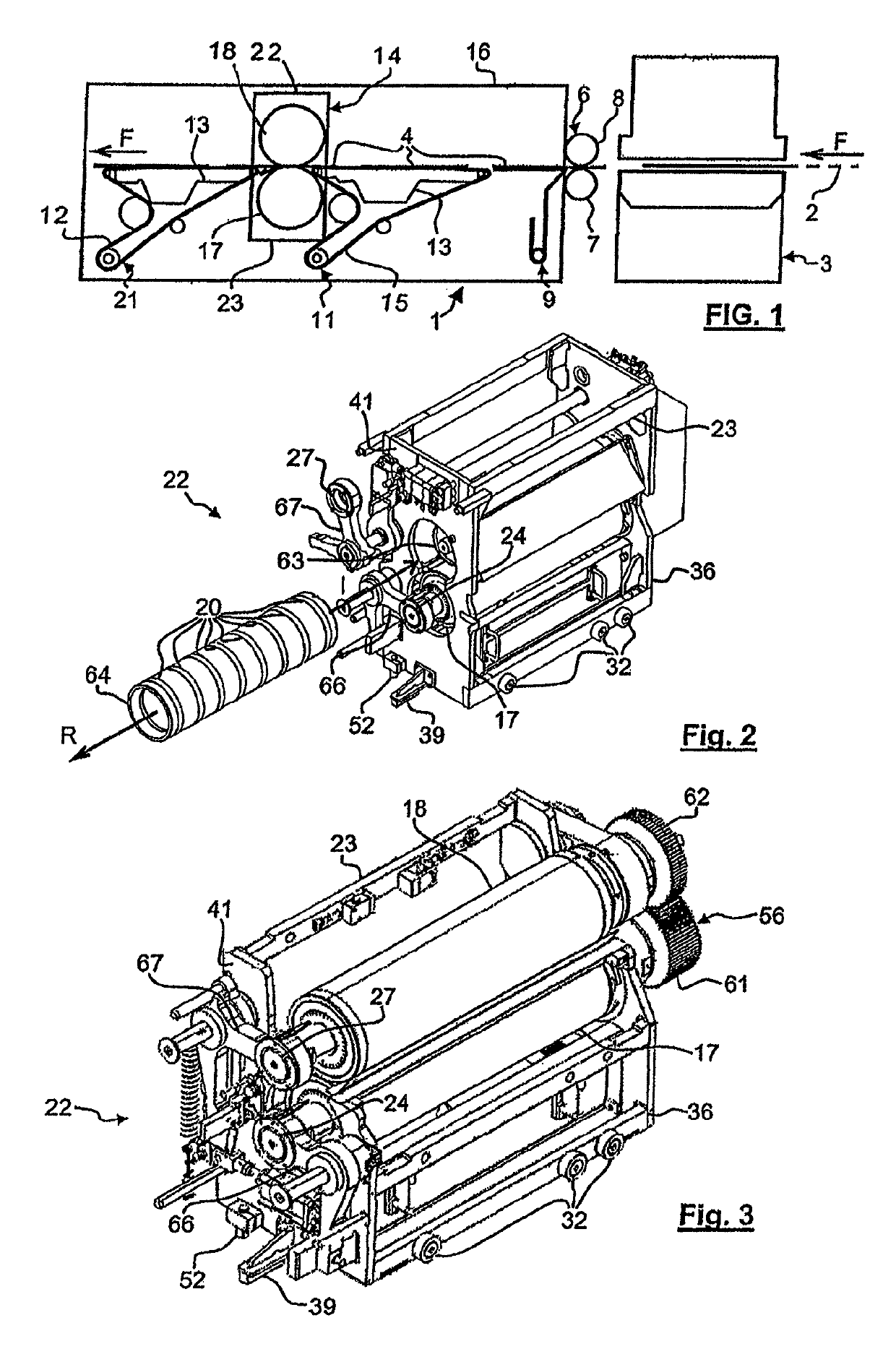
[0033]As FIG. 1 shows, a packaging production machine (1) processes a substrate or a material in a continuous strip (2), which is in this example flat cardboard. The machine (1) comprises a transformation unit, for example a diecutting platen press (3). Upstream of that press (3), the machine (1) may have units such as printing units, means for checking quality and register, embossing units, etc. (not shown).

[0034]The strip (2) enters into the press (3) from its upstream transverse side. The press (3) cuts the strip (2) and delivers the substrate in the form of blanks (4), made of flat cardboard. The blanks (4) leave the press (3) by its downstream transverse side. The direction of progress or of advance (arrows F) of the strip (2) and of the blanks (4) in the longitudinal direction indicates the upstream direction and the downstream direction.

[0035]The machine (1) includes a drive arrangement (6), which is arranged downstream of the press (3). This arrangement (6) firstly comprises...


PUM

PropertyMeasurementUnit
weightaaaaaaaaaa
flexibleaaaaaaaaaa
displacementaaaaaaaaaa

Abstract

A waste stripping unit in a packaging production machine (1), positioned downstream of a cutting unit (3). The stripping unit includes a frame and two rotary tools cooperating with one another (17, 18). A first tool has waste stripping needles protruding radially outward from the outer surface. The two tools (17, 18) are mounted in a removable cassette (22). A frame (23) is provided with bearings supporting the two tools (17, 18), and which can be introduced into, attached to and extracted from the frame (16).

Description

CROSS-REFERENCE TO RELATED APPLICATIONS[0001]The present application is a 35 U.S.C. §§ 371 national phase conversion of PCT / EP2010 / 002930, filed May 12, 2010 which claims priority of European Application No. 09006447.8 filed May 13, 2009, the contents of which are incorporated by reference herein. The PCT International Application was published in the French language.BACKGROUND OF THE INVENTION[0002]The present invention relates to a waste stripping unit for stripping waste obtained by cutting a flat substrate. The invention also relates to a waste stripping unit that facilitates any stripping tool adjustment. The invention also relates to a packaging production machine comprising, in order and in succession, a cutting unit and a waste stripping unit. A packaging production machine is intended for the manufacturing of boxes, which form packaging after folding and gluing. In this machine, an initial flat substrate, such as a continuous strip of cardboard, is unwound and printed by a ...

Claims


Application Information

Patent Timeline
Patent Type & Authority Patents(United States)
IPC IPC(8): B21B31/10B26D7/18B31B50/00B31B50/20
CPCB21B31/103B26D7/1836B31B2160/102
Inventor COMPAGNONE, GIOVANNICORMINBOEUF, GLENN
Owner BOBST SA
Learn More